In the early 1980s the Army had its new medium helicopters in production. Sikorsky was building the UH-60 Black Hawk utility helicopter and Hughes (later to be McDonnell and then Boeing) was producing the AH-64 Apache gunship.
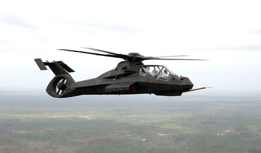
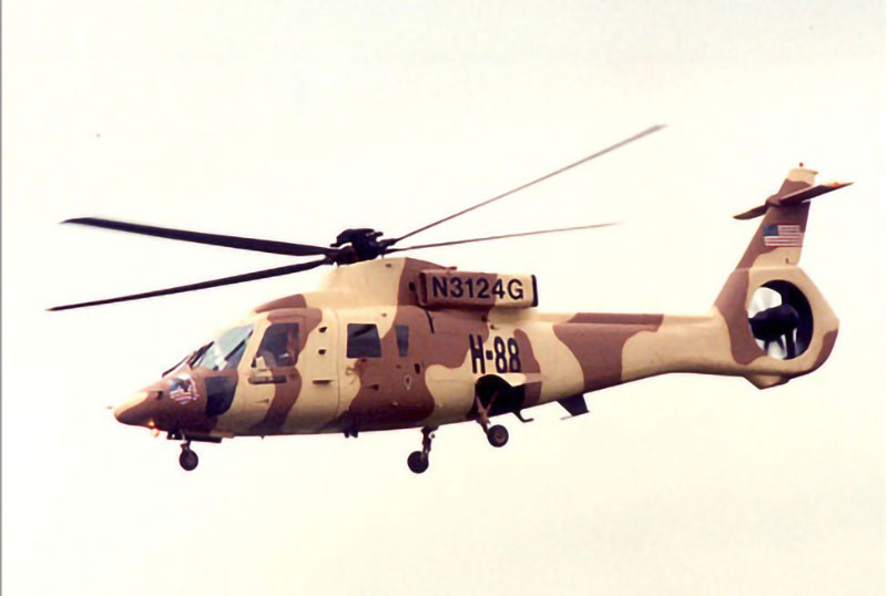
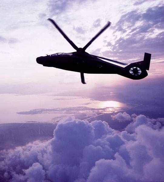
The Boeing Sikorsky RAH-66 Comanche
They then turned their attention to replacing their smaller helicopters, the Vietnam-era Hughes OH-6 and Bell OH-58. They also wanted a small utility helicopter and gunship similar to the Bell UH-1 Huey and AH-1 Cobra in their original forms. They envisioned one new dynamic system (rotors, engines, transmissions, and controls) which could be applied to both utility and gunship fuselages. The aircraft was named the LHX, for Light Helicopter Experimental.
Much of the 1980s was spent on conceptual design studies. These included aircraft configuration – conventional helicopters versus higher speed concepts – single versus dual pilots; and various approaches to the mission equipment package.
Based on Vietnam experiences the Army was strongly motivated to make the LHX more survivable. That became a strong contributor for the LHX requirements, requiring high levels of maneuverability and low levels of detectability, both of which strongly influenced the design.
As the program evolved it became clear that much new technology was available beyond that of the early 1970s when the Black Hawk and Apache designs were defined, to meet these requirements. Primary of these were the ability for low radar and IR signatures, and the new structural technologies of composite and advanced metallic materials. There was also a new emphasis on low acoustic signature. Plus great advancements were being made on sighting, targeting and weapons systems, computer computational power, and advanced digital control systems.
Special emphasis was placed on supportability and total life-cycle costs. It was thought that these had not received sufficient emphasis in the early design stages of previous programs, and that substantial gains were possible if these disciplines were considered early in the conceptual design phase.
A total production run of about 6000 aircraft was projected. This was thought to be too much for any one manufacturer and the Army directed the four major helicopters manufactures (Bell, Boeing, McDonnell and Sikorsky) to form two two-company teams for a competition. Sikorsky and Boeing were the first to join together as a team which they announced in 1985. They named themselves the Boeing Sikorsky First Team. Bell and McDonnell then combined to become the competing team, which they named the SuperTeam.
The Army developed a requirement for the LHX to have an empty weight of 7,500 pounds or less, and a maximum average production cost of $7.5 million. They also concluded that there was no need for speeds above those of conventional helicopters, and discussions of higher speed concepts ceased.
The Army next decided that the goal of developing both utility and recon/gunship configuration was probably too ambitious, and the utility configuration was dropped.
In the Boeing Sikorsky teaming agreement Sikorsky was the lead on the airframe, air vehicle integration, simulation, and final vehicle assembly. Boeing was the lead on the mission equipment package (MEP) and integrated logistics support (ILS). But each company would take a portion of the other’s lead. Boeing was assigned to do the flight control system, the main rotor blades and the tail of the airframe. Sikorsky did the helmet sighting and tracking system of the MEP.
The Boeing Sikorsky First Team included a number of other industry-leading companies to develop this complex mission system aircraft. These included:
Digital map
Controls and displays
High speed data bus
Sensor Data Distribution Network (SDDN)
Wide field-of-view helmet mounted displays
Helmet tracking
Martin Marietta
Target Acquisition System (TAS)
Night Vision Pilotage System (NVPS)
Longbow Fire Control Radar (FCR)
TRW
Integrated Communications Navigation and Identification Avionics (ICNIA)
Aircraft Survivability Equipment (ASE)
Processors
Automated targeting detection and classification
Westinghouse
ATD/C
Aircraft Survivability Equipment (ASE)
Longbow missiles Boeing A&E
A number of these team members would change as the program developed.
In October 1988 the U.S. Army awarded the Boeing Sikorsky First Team and the McDonnell Bell SuperTeam contracts for the initial phases of the demonstration/validation program, during which the teams formulated their LHX designs and demonstrated elements of those designs for the Army.
In the fall of 1990 the competing teams submitted proposals detailing their designs and a plan for developing and producing the aircraft. In February 1991 the teams submitted best-and-final offer proposals committing themselves to the next phase of the program, which called for building and flight testing LHX prototypes in 1994.
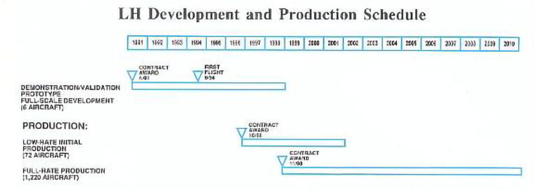
On April 9, 1991 the U.S. Army announced that the Boeing Sikorsky First Team had been selected to develop and produce the LHX. By this time the projected aircraft production quantity had been reduced to 1,300. Total program cost was estimated to be more than $30 billion. The contract between the Army and Boeing Sikorsky was for full-scale development. The first production LHX was scheduled for delivery to the Army in 1998.
1991 planned program schedule
As the program progressed this schedule was delayed many times as a result of the Army reducing the yearly funding and adding additional requirements.
Also at this time, the Army changed the name of the program from the LHX – for Light Helicopter Experimental – to the LH – for Light Helicopter.
The Roll-Out of the first Comanche aircraft occurred on May 25, 1995 and first flight was on January 4, 1996.
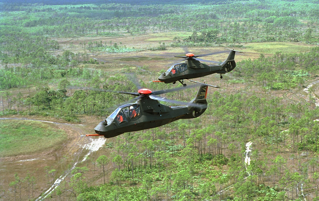
Despite the challenges considering the unconventional nature of the aircraft design, the flight test program was generally successful. This was the result of the extensive detailed development program conducted prior to the first flight. There were no major incidents, and the basic aircraft met or exceeded all operational objectives. Forward flight speeds in excess of 200 knots were achieved, and the aircraft exhibited astonishing capabilities in sideward and rearward flight. It could easily reach speeds in excess of 60 knots sideways, and 80 knots rearward, while maintaining full controllability.
Aircraft #1 and #2 in flight
By the end of this flight test period, in March 1997, the aircraft had gone to 10,000 ft., 1.7 g’s load factor and 120 knot autorotation, all in the AFCS (Automatic Flight Control System) mode of flight.
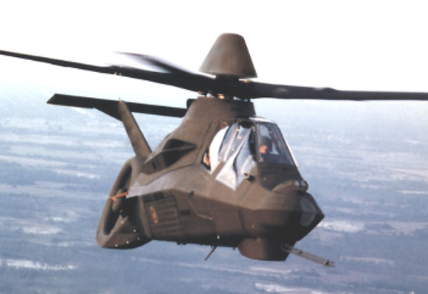
The only major technical issue that came up with the air vehicle was the configuration of the tail. The initial design had weak directional stability and was determined to be not acceptable. In December 2000, a revised tail was flown with a simulated version of the Longbow radar (which had recently been added to the Comanche’s requirements), a new main rotor pylon, an updated rotor hub fairing, and vertical tail end plates on the horizontal tail. These modifications were concluded to be successful.
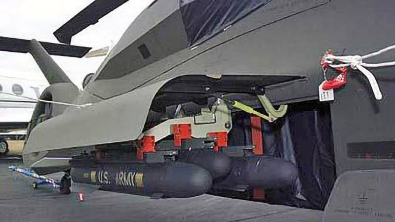
Flight test with dummy Longbow
During the thirteen years of the program, support from the Army, DoD and the Congress vacillated. Initially support was strong and the funding was approved in 1991 for the Demonstration/Validation Full Scale Development phase. However a few years later the yearly funding was reduced, requiring a stretch out of the schedule and a full program restructuring. This happened three more times before the Full Scale Development Program was successfully concluded in 2000. In a number of these restructuring efforts additional requirements were added, or the mission equipment systems were redefined to incorporate further advances in technology, thus growing the aircraft weight and cost.
The next step in Comanche development was the EMD (Engineering and Manufacturing Development) phase. Quoting an article in the internal Sikorsky magazine, Inside Sikorsky, from April, 2000:
“…on April 4, the U.S. Army released its long-awaited 2000 Aviation Force Modernization Plan which calls for fielding COMANCHE on schedule starting in 2006…The plan calls for full procurement of 1,213 aircraft, worth about $34 billion over the full production cycle. The plan cited COMANCHE as the linchpin of the Army’s aviation modernization efforts.
“,,,‘Reconnaissance/security represents the single greatest deficiency in Army aviation’ the report noted. ‘The Army remains completely committed to the COMANCHE, a variant of which may be considered as the possible long-term solution for the attack helicopter beyond Apache Longbow.’
“When briefing news reporters about the modernization plan, Army officials reiterated the service’s support of COMANCHE…‘ This plan provides a significant departure from the past because it aligns the aviation strategy with the Army vision. It places the COMANCHE as the centerpiece of Army aviation modernization,’ said BG Craig D. Hackett, the Army’s Director of Requirements for the Assistant Deputy Chief of Staff for Operations and Plans – Force Development.”
The contract for EMD was signed on June 1, 2000. Contract value was $3.1 billion. The program was to manufacture and deliver five Comanche helicopters for EMD testing, and deliver eight aircraft to the Army for operational test and evaluation. Testing was to include qualifying the fully integrated digital mission equipment package and advanced cockpit management systems, incorporating navigation, communication and target acquisition capabilities. Low-rate initial production was scheduled to begin in FY2005, with a ramp up to planned full production, 72 per year, with Lot 6 in FY2010. Final delivery was slated for 2023. The first U.S. Army Comanche unit was projected to be operationally equipped in 2006.
This was the first time in twenty years that an Army aircraft program had reached the EMD phase.
As EMD commenced, aircraft #1 continued on flight test and completed its flight testing at the end of 2001. It had flown 311 flights for a total of 377.5 hours. It had tested the more powerful LHTEC T800-LHT-801 engines, with a 17% power increase to 1,563 horsepower. It was then taken off flight status to be used as a backup for aircraft #2. At that time aircraft #2 had flown 103.5 hours and would continue in flight test, concentrating on the MEP.
In the spring of 2002 the Lockheed Martin Night Vision Pilotage System was delivered for integration into the aircraft. It included the helmet displays, commercial processors, and functional cockpit displays. The Target Acquision System and other MEP elements were to be incorporated later.
Aircraft #2 made its first flight with new MEP software and the more powerful engines on May 23, 2002. The MEP software provided the foundation for the aircraft operating system and would support the pilotage, vehicle systems reporting and health, and the digital map function.
In the second year of the EMD program contract questions were raised as to whether the contract could be completed as planned. After numerous analyses were conducted, both the Army and Boeing Sikorsky concluded that the program’s cost and schedule metrics indicated that the program could not be completed as planned. Another restructure would be required. This was the only one of the five program restructures which was not a result of government actions to reduce or stretch out the funding profile.
According to the spring 2002 issue of Vertiflite, the restructure called for the first EMD aircraft to fly in 2004. Each of the five EMD aircraft was to be a different configuration to mature different subsystems. The first LRIP (Low Rate Initial Production) aircraft was to be near production standards from an air vehicle standpoint and fully equipped for the armed reconnaissance mission. Block upgrades would then expand the mission equipment package, making additional technology insertions based on evolving Army requirements. Initial Operational Test and Evaluation (IOT&E) was planned for 2007. The Comanche Initial Operational Capability (IOC) would include 12 aircraft and occur in 2008. Production quantity was reduced from 1,213 to 650, with a peak annual build rate of 60 aircraft per year. Production would run until 2019.
The restructure added $3.4 billion to the $3.1 billion EMD program and delayed fielding of the aircraft to late 2009. The additional funding came out of the planned Comanche funding line, and resulted in the Army buying 126 fewer aircraft to free up the money.
On November 14, 2002 the contract for an additional $3.4 billion in development funds was signed.
The Comanche’s long development schedule created a number of issues. The August 25, 2003 issue of Aviation week mentions a processor upgrade that “…would try to keep pace with the advances made in the commercial computer sector.” This was projected to require significant rewriting of the software code, at another additional cost.
The numerous restructures with expanded requirements resulted in the aircraft empty weight growing from 7,500 lbs. to 9,300 lbs. The primary mission gross weight grew from 10,088 lbs. to 12,350 lbs. This required a more powerful version of the T-800 engine and a growth of the rotor diameter from 39 ft. to 40 ft. What started out to be a modern replacement for the AH-1 Cobra grew to becoming close to an AH-64 Apache replacement.
In a hint of things to come, the New York Times reported on April 15, 2002 that “Defense Secretary Donald H. Rumsfeld convened a meeting with the three service secretaries today to tell them they needed to cut major weapons systems to finance new ‘transformational technologies,’ including space surveillance systems and unpiloted weapons, officials said. Big-ticket programs potentially on the block, beginning with the 2004 budget, include the Air Force’s next-generation tactical jet and two Army weapons, the Comanche helicopter and the Crusader artillery system, officials said.”
In an announcement on February 23, 2004 the Defense Department stunned both the Army Comanche team and Boeing Sikorsky with an announcement that it was terminating the Comanche program. This was after they had recently cancelled the Army’s Crusader mobile artillery system. The Army web site said that they ended the program based on experience during combat in Afghanistan and Iraq, and a high-level drive to make the branch better at fighting counterinsurgency and unconventional warfare campaigns.
In his closing remarks at a February 23, 2004 Army press conference, Lt. Gen Richard A. Cody, Army Deputy Chief of Staff, said “…I think I’m the only general officer that’s flown the Comanche. And I will tell you up front, and pass on to my friends at Boeing and Sikorsky that are on this team, they built a tremendous aircraft. It is the most flexible, most agile aircraft that we have produced in this country, and the people that built it ought to be very, very proud of it. Tremendous flying characteristics and leap-ahead technology that’s going to help us as we move forward.”
Configuration Features
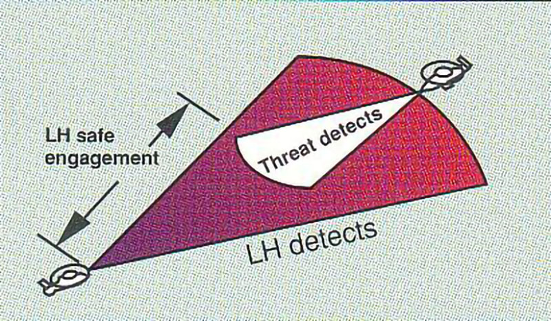
The basic configuration advantage of the Comanche was it ability to “see without being seen”. With low observables to make it difficult to detect, the latest technology in sighting and targeting systems to extend their operating range and their speed of operation, and the ability to communicate this data to all on the battlefield, Comanche was the first helicopter that could detect targets without being detected itself. This was a long way from the Vietnam-era helicopters where the enemy knew a helicopter was approaching long before it got there, simply from its acoustic signature.
See without being seen
Both the radar and IR signatures were well below the Army specifications. Although the actual detectability signatures are classified, general levels of signatures were released, comparing the Comanche to the existing technology:
Radar
100 times better
Infra Red (IR)
15 times better
Acoustics
6 times better
Visual
10% smaller
Comanche achieved its low radar signature by fuselage shaping, the use of radar absorbing materials and locating the mission armament and landing gear within the fuselage. It did not require any RF jammers.
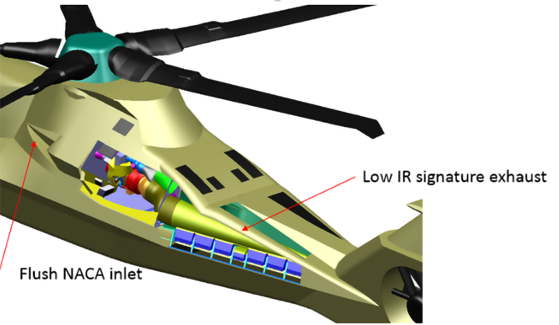
Low IR signature was achieved by using a unique engine exhaust system which ducted the exhaust into the tailcone where it was mixed with cool ambient air before it exited the aircraft. No IR jamming equipment was required.
Acoustic signature reduction was achieved by using a variable-speed five bladed main rotor with thin blades and a low tip speed. The Fantail antitorque system was specifically designed to eliminate the “siren” effects of existing tail fans, and again by using geometries specifically designed to reduce noise.
To reduce the visual signature the aircraft was kept small and specific considerations were applied to reduce canopy glint. The five blades also reduced the “flicker” effect.
On sighting and target acquisition, the Comanche systems had a usable range 40% further than systems then currently in use. The second-generation FLIR (Forward Looking Infra Red) could detect temperature differences smaller than the systems then in use. Again, the actual values are classified. The helmet mounted displays included image intensifiers which were designed with fully operational, separate displays for the pilot and copilot. They had a 31% larger field-of-view than existing systems. A digital map was provided using Defense Mapping Agency (DMA) digital terrain on optical discs.
The aircraft was capable of single-pilot operation from either seat.
For protection against nuclear, biological, and chemical threats Comanche used pressurized cockpits and electronics compartments. A unique maintenance-free pressure swing adsorber cleaned the incoming air without the use of replaceable filters. The smooth composite fuselage exterior was designed to not deteriorate when decontamination cleaners were used.
Electromagnetic pulse tolerance was 20 times better than existing aircraft.
Ballistic tolerance was projected to be 50 times better than existing helicopters. Multilevel redundancy and self-healing provided virtual invulnerable electronics. The airframe and rotors were ballistically tolerant and field-repairable.
High levels of crashworthiness were a design requirement for the landing gear, airframe structure, crew seats, and fuel system.
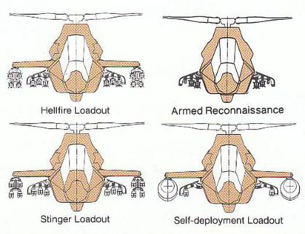
For the basic armed reconnaissance mission Comanche carried four Hellfire and two Stinger missiles in internal compartments, and 320 rounds for the nose-mounted gun. For the air combat mission two Hellfires, four Stingers and 500 rounds were employed.
Armaments ExtendedArmament loadout options
For a full Hellfire loadout an external stores rack was installed which could hold eight additional Hellfires. Or, additional stingers could be carried.
The external rack was also used for two range extension tanks for self-deployment ferry missions up to 1260 nm range.
The Comanche was designed for air transportability in a number of Air Force transports. It met or exceeded the entire required load and unload timelines.
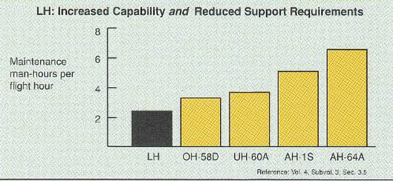
Supportability was a high priority for the Army to reduce operations and support costs and to improve aircraft availability in the field. Comanche’s unique fuselage design permitted judicious locations for doors and access panels, easing the maintainer’s job. Two maintenance levels were planned compared to three for the existing fleet. A 40% reduction in maintenance burden was projected compared to the existing fleet.
The following describes the Comanche at the time of the Full Scale Development proposal, August 31, 1990. Some of this was altered as the program proceeded.
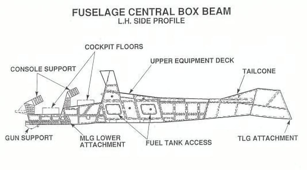
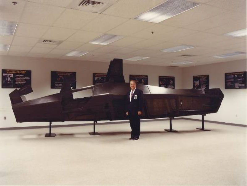
The Fuselage After many conceptual design studies, the Boeing Sikorsky team chose an unusual design for the fuselage. Unlike virtually all other helicopters (and fixed wing aircraft for that matter) it was decided not to use the exterior surfaces of the aircraft for the primary fuselage structure. Because of the need for a low radar signature, the aircraft weapons had to be stored within the fuselage and then extended out when they were to be deployed. LHX also required a retractable landing gear for both low radar signature and for high speed. Additionally, the Army’s emphasis on supportability required many access panels to simplify maintenance tasks. It became apparent that a conventional fuselage would be very structural inefficient (i.e. heavy and flexible) and difficult to design. An alternate approach was created to have a simple structural box beam internal structure with the outside skin unloaded from the primary structural loads. Doors and access panels could then be placed in the most optimum positions, improving both radar signature and ease of maintenance for the internal components.
Early in the program this started to be described as the “fuselage within a fuselage” with some derogatory implications that it must be too heavy. In actuality, it became one of the most positive attributes of the Boeing Sikorsky design.
Bruce Kay, Sikorsky Chief of Design, with fuselage skin display
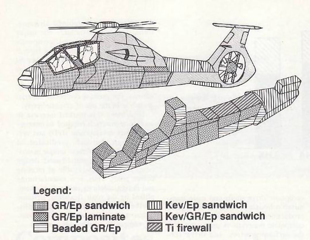
Extensive use of advanced materials, primarily composites, was a key to lowering production cost and aircraft weight.
Use of advanced materials in the fuselage
The Main Rotor System Advances in technology lead to a new concept for the main rotor, the bearingless main rotor, or BMR. This was a simple flexbeam which replaced the conventional flapping, lead-lag, and pitch change bearings of existing helicopters. Early helicopters had metal bearings for all three motions and these were grease lubricated. This then lead to oil lubricated bearings to reduce maintenance requirements. In the 1960s a concept was developed to replace these conventional bearings with elastomeric bearings that require no lubrication; first being used on the Sikorsky CH-53D and then on the UTTAS/Black Hawk.
The Black Hawk tail rotor was the first production use by Sikorsky of the flexbeam concept. It used two graphite flexbeams connecting two rotor blades, clamped together for the four-bladed rotor. The LHX applied the flexbeam approach to the main rotor.
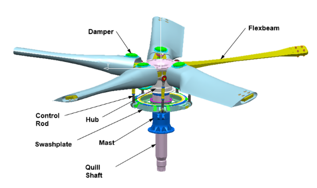
The Pentaflex rotor
Conventional hinged rotors have a specific hinge offset – the ratio of the flapping hinge position radially as a percentage of the rotor radius. This strongly affects the rotor control power and dynamic characteristics. Helicopters then in production had hinge offsets from 0 to 5 percent. Bearingless rotors have the same attribute, using the term “equivalent offset” to compare them to hinged rotors. Because LHX was to be a very maneuverable aircraft, a high equivalent hinge offset was desired. Boeing Sikorsky chose a 10% equivalent offset to get the agility desired for LHX.
A decision was made to use five rotor blades to reduce individual blade forces and moments as well as to improve the rotor’s acoustic signature. Thus the rotor was called a “Pentaflex”. Variable speed was also used to help control the acoustic signature. This was accomplished by varying the engine speed.
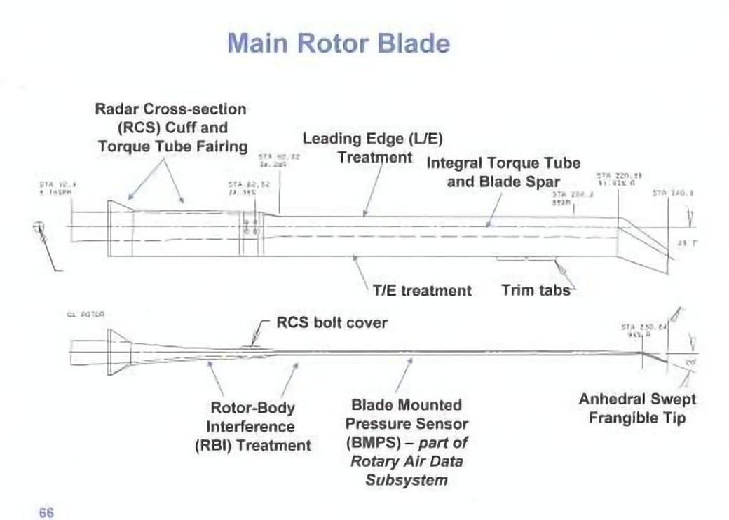
The rotor had a diameter of 39 ft. Blade chord was 15 inches. Twist was -11.1˚, or -13.5˚ on a thrust weighted basis. The blade out to 85% radius used a Boeing 10% thick VR-12 airfoil. This transitioned by 90% radius to a Sikorsky 9% thick SSC-A09 airfoil. The outer 8 percent of the blade was swept and tapered. The SSC-A09 airfoil for the tip was chosen because it had a high maximum lift coefficient and a high drag divergence Mach number.
The main rotor blades were all composite, based on proven low-risk Boeing production designs. They had also been proven to be ballistically tolerant to 23 mm rounds.
The Tail Rotor System The Army defined a very high level of yaw control power for the LHX due to the limitation of their current light helicopter fleet when flying at high altitudes. In many conditions the current helicopters simply ran out of tail rotor control power at altitude.
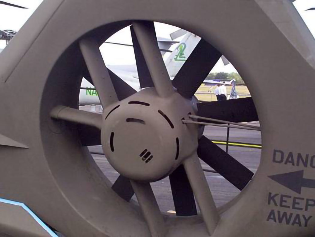
The stated requirement was to perform a 180º yaw turn while flying sidewind at 45 knots. This lead to a much larger antitorque/yaw control system than the industry was used to. In addition, the army required a “protected” antitorque system to prevent personnel accidents where soldiers ran into the tail rotor under stressful combat conditions. A conventional tail rotor was not acceptable.
The Boeing Sikorsky solution was the 4.5 foot diameter “Fantail”, a ducted fan design with personnel barriers. The ducted fan approach was not immediately seen as an advantage due to the use of this concept on other production helicopters; they were louder than open tail rotor helicopters. A simple analysis showed that the noise was due to supporting struts being located too close to the fan, in essence creating a siren effect. With sufficient clearance between the fan and the struts, the noise was very acceptable. Sikorsky constructed a Fantail and flew it on an S-76 helicopter to prove this point and the other advantages of the Fantail.
The Fantail anti-torque/yaw control system
An interesting fallout of the very high control power of the Fantail was the creation of a new flight maneuver. One requirement by the Army was to do a quick turn-to-target maneuver at moderate speeds. This was expected to be a roll into a 90º turn, turn, then roll out and line up with the target. Flight testing showed that the Boeing Sikorsky LHX could simply yaw 90º at speeds up to 70 knots to meet this requirement. No extreme rolling required. This maneuver was named the “snap turn”, and became a favorite of pilots flying the aircraft.
The Fly-By-Wire Control System The Army generated a new focus on air superiority for LHX with new requirements for high levels of maneuverability across all aircraft operations to improve its survivability. The Boeing Sikorsky design reflected a response to that new focus with specifically scripted fly-by-wire control laws as well as the rotor system design choices.
The Comanche digital fly-by-wire flight control system (FCS) was the most advanced rotorcraft flight control system that had been developed at that time. Several of the features greatly improved handling qualities and reduced pilot workload. Additionally, the digital fly-by-wire system promised to be more reliable and weighed significantly less than a redundant mechanical system. The Comanche FCS provided two highly augmented modes: rate command/attitude hold, which provided very responsive maneuver capability for day visual conditions, and attitude command/velocity hold, with more benign response for night and degraded visual conditions. The system incorporated a number of automated features including a flight director and a fully coupled auto-pilot with advanced functions, including auto hover, pop-up, and return to mask. Functions that were to be added in later stages of the program included envelope cueing and integrated fire and flight control. Use of a triplex (triple redundant) electronic architecture with wires in lieu of mechanical linkages provided greater flexibility in routing the wiring and reduced the probability of ballistic damage from threat weapons.
The navigation function was integral to the flight control system and relied on three inertial/Global Positioning System navigators to develop the navigation solution.
Engines The Government ran a competitive program to develop a new advanced technology engine for LHX in parallel with the development of the aircraft. The competition ended with the LHTEC team of Honeywell and Rolls Royce being awarded a contract to provide their T-800 engines. This engine had a maximum contingency power rating of 1399 horsepower, and weighed only 315 pounds. The specific fuel consumption was a low 0.459 lb./hr./shp. It had a Full Authority Digital Engine Control (FADEC) that was compatible with the Comanche fly-by-wire control system. The engine was designed to be maintained with only a simple flight line hand tool kit.
Comanche was actually a three engined helicopter. Power for the rotor drive system was provided by two LHTEC T-800 engines. A Williams International WTS124 secondary power unit (SPU) provided auxiliary power to start the main engines, and in flight provided bleed air to run the environmental control system and power to run one of the electrical generators and a hydraulic pump.
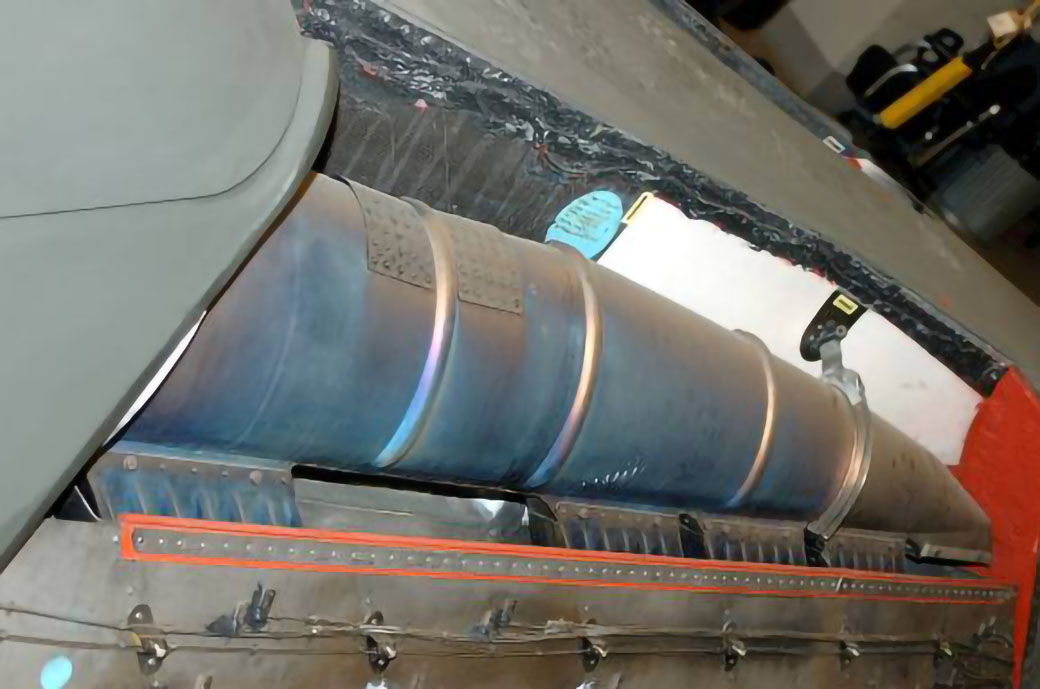
Infrared Suppressor System The IR signature was reduced by using a unique engine exhaust system which ducted the exhaust into the tailcone where it was mixed with cool ambient air before it exited the aircraft. This system demonstrated an IR signature one-half of the Army specification level. No IR jamming equipment was required.
The infrared exhaust systemExhaust tailpipe
Biological and Chemical Protection and the Pressure Swing Absorber (PSA) For protection from biological and chemical agents the Comanche cockpit and electronics compartments were pressurized slightly above ambient pressure so that if there was any leakage it would be out of the aircraft rather than in. This was designed to work properly even if there was a bullet penetration of the structure.
To filter out hazardous chemical agents, a novel Pressure Swing Adsorber (PSA) was incorporated. The pressure swing adsorption process relies on the fact that under high pressure, gases tend to be attracted to solid surfaces, or “adsorbed”. When the pressure is reduced, the gas is released, or desorbed. This was the first time that a PSA was used in an aircraft environmental control system.
Comanche’s PSA contained two chambers that were filled with porous media. Each chamber contained a series of molecular sieve beds that were designed to filter out threat chemical agents. Pressurized air was passed through one chamber, to adsorb the noxious gasses. The clean air was then distributed to the cockpit and protected avionic compartments. A portion of the clean air also passed through the second chamber, at a lower pressure, and then vented overboard. The lower pressure air caused the filtered gasses to become desorbed, thereby cleaning the chamber, and allowing it to become an adsorber again. This process was continuously cycled back and forth to provide a steady supply of clean air.
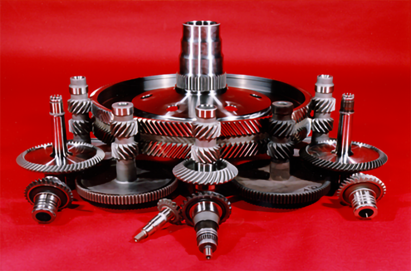
The Transmission System The transmission system also made use of major technology advances since the previous generation of helicopters. Transmission designers of even moderate sized helicopters face a difficult challenge designing the final reduction stage of the drive system. Since the rotor turns a relatively low speed (200 to 400 rpm) the torque in the final stage is very high. A final reduction stage of a simple spur or bevel gear is impossible since the tooth loads on that single gear mesh are excessive. Years ago this problem was solved by using a planetary final stage, typically with five planet gears, to transmit the high torque to the rotor through five separate gears. With LHX a simpler system was used using the concept of “split torque”. Here each of the two engines had a split path to the final reduction stage, resulting in four gears meshing with the final ring gear to transmit the high rotor torque without the use of a complex planetary gear stage. This resulted in 50% fewer gears, 40% fewer bearings, and 12% less weight.
Split Torque main gearbox
As this design evolved, another advantage soon became apparent. Intermediate shafts in the drive system were vertical and turning at speeds appropriate to drive the hydraulic pumps and electric generators. Thus they became the mounting pads for these accessories. This eliminated the need for a conventional accessory gearbox, and mounted pumps and generators in a position where they were very accessible to the maintainer.
The Electrical System A 270VDC electrical system was used. There were three main 30kw generators; two driven by the main gearbox and one by the SPU. Two additional hydraulically driven HPMGs (Hydraulic Permanent Magnet Generators) were dedicated to powering the flight control computers.
The Hydraulic System A 3000 psi hydraulic system was used, with three independent subsystems. Two of these were for the flight controls, including the HPMGs for the flight control computers. The third was a backup for the other two and drove various utility functions including the landing gear and weapons bay door deployments. System 3 was also used for ground run-up. Like the electrical generators, two hydraulic pumps were mounted on the main gearbox and one on the SPU. A hydraulic intensifier was used to provide 5000 psi hydraulics for the SPU startup and for landing gear emergency blow-down.
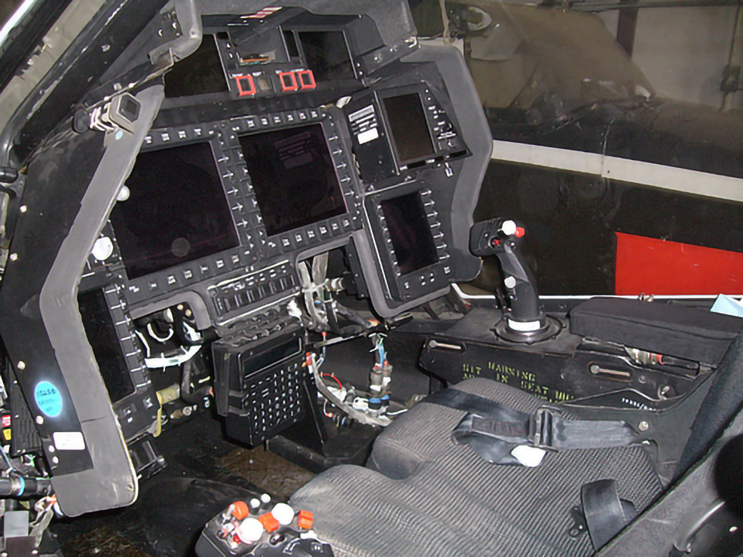
Crew Station Comanche had a two-person tandem cockpit. They were identical and the aircraft was fully operable by one pilot from either station. The flight controls were fly-by-wire with a right sidearm controller for pitch, roll, and yaw control. A left side collective pitch controller was used. Pilots had a 30˚ by 60˚ field of view NVPS (Night Vision Pilotage System) and a dual independent IITV (Image Intensified TV) system. Helmet-mounted displays provided all data and displays for eyes-out flying and fighting with a 35˚x 60˚ field of view. Seats were armored and crashworthy.
Comanche cockpit
Mission Equipment
The Mission Equipment Package (MEP) for Comanche consisted of:
A Night Vision Pilotage System (NVPS)
A Target Acquisition and Designation System (TADS)
A Helmet Integrated Display and Sighting System (HIDSS) in each cockpit
An Integrated Communications, Navigation and Identification Avionics (ICNIA) Suite
Four head-down LCD Multi Purpose Displays in each cockpit station
A Terrain Mapping and Display system
Plus dual mission computers and systems to make all this functional
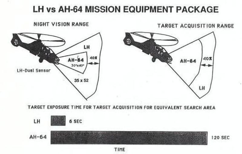
MEP performance compared to the AH-64 in 1991
Night Vision Pilotage System, NVPS
The “see” part of “see without being seen” came from the Target Acquisition System (TAS) and the Night Vision Pilotage System (NVPS). These were mounted on the nose of the aircraft to provide maximum field of view, a view unobstructed by the rotor, and to reserve the mast-mounted position for future inclusion of the Longbow system. They included both a Forward Looking InfraRed system (FLIR) and a Low Light Level TV (LLLTV). The NVPS provided both navigation and reconnaissance capabilities, was capable of night nap-of-the-earth and terrain avoidance flying in adverse weather conditions, and gave a clearer definition of the horizon than previous systems.
The FLIR at that time was “second generation” and could detect smaller temperature differences than earlier FLIRs. (The actual temperature numbers are classified.) It also included an image intensifier function. It had a 30º by 60º sensor field of view, and a 35º by 60º field of view as displayed on the pilots’ Helmet Mounted Display (HMD). This was a 31% increase over what was then being used on the AH-64 Apache. The visual range of the system was a 40% increase over the Apache.
Target Acquisition System, TAS
The target acquisition system had the same advanced features as the pilotage system, with a second generation FLIR and a 40% increase in standoff and detection range. Also, it included a heads-up, eyes-out helmet-mounted display, and the ability to work in adverse weather conditions and with battlefield obscurants. It also had an Aided Target Detection and Classification (ATD/C) function with files of known enemy vehicles which could be compared with the view being received. This included a search-on-the-move function; moving target detection; and automatic multitarget prioritization, tracking, weapons selection and fire control. Hover search times were less than six seconds; scene review was conducted after the aircraft had remasked. When a match was found, this information was displayed to the pilots, and a weapons cueing/rangefinding function initiated. This resulted in a 95% reduction in target acquisition time and three times more target location accuracy compared to systems then in use. False alarm rates were projected to be five times lower than the Army’s requirement.
Helmet Mounted Display
The HMD included individual, independent bi-ocular wide-field-of-view displays with image intensifiers. Symbology for heads-up and eyes-out operation was included. The imagery consisted of sensor video from the Night Vision Pilotage System (NVPS) or the Electro-Optic Target Acquisition and Designation System (EOTADS) and video from the helmet mounted image intensifier sensor. Symbology consisted of flight graphics and alphanumerics which were overlaid over the imagery.
Integrated, Communication, Navigation, and Identification Avionics, ICNIA
The Integrated Communication/Navigation/Identification system included Global Positioning (GPS) navigation with accurate back-up provided by both Doppler and inertial inputs to assure mission completion. The navigation system was fully coupled to the flight control system to provide automatic flight along selected waypoints. Navigation and tactical overlays were provided on a digital map for tactical awareness and easier, more thorough mission planning. Optimum route selection was updated in real time. Target data could be transferred from the aircraft to the tactical operation center. The system was designed to be highly fault tolerant, reliable and survivable. It was designed for straightforward future growth.
Mission Electronics
The mission electronics used highly redundant, fault-tolerant architecture. They included 33-bit processors, an 800-Mbps sensor bus, a 50-Mbps data bus and dual 1553 data buses. It was projected to have a 95% level of automatic fault detection and a 98% level of automatic fault isolation to the line replaceable unit (LRU) level. Electronic racks were installed in the rear of the fuselage at waist-high level where they were easy to access for maintenance. Compartments on both sides of the aircraft provided separation for improved survivability. Racks were sealed and cooled with filtered air. They were pressurized for moisture- and NBC-protection. The design included 30% spare processor capability and a 50% bus throughput margin in reserve. 14 open rack positions were included for new modules and capabilities, such as the LONGBOW preplanned product improvement. Modular electronics is located in the tailcone for ease of maintenance and growth
They also included embedded programs for in-cockpit training of the various systems.
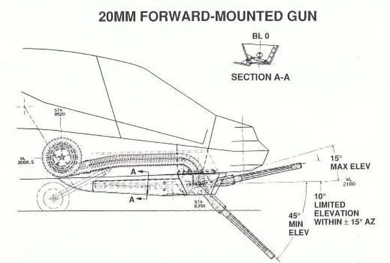
Nose-Mounted 20-mm Gatling Gun
A 20-mm Gatling gun was mounted below the cockpit. It swiveled in a 240º arc for firing at passing targets. It could fire up at 15º and down to -46º. It could rotate 180º for stowing in a low observable position. The ammunition path was carefully designed to avoid jams and for easy loading. Two rates of fire were available: 750 or 1,500 shots per minute. Dynamic boresighting could be done in flight.
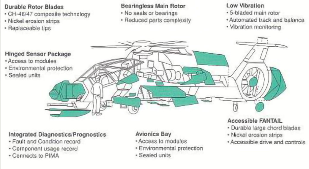
Supportability
The Army had a strong interest in improving the supportability of its aircraft due to a history of high operational and support costs and poor aircraft availability. It wrote into the LH specification specific requirements to meet this goal. The Boeing Sikorsky team responded by putting supportability engineers with the design engineers as the design was created and throughout the DEM/VAL program.
Many of the initial design decisions were the result of supportability considerations. Technology allowed simpler designs which inherently improved supportability, but other decisions were made in the favor of supportability even if they had an adverse impact on other aircraft attributes like weight.
Supportability considerations in the aircraft design
The Army’s three-level maintenance system was reduced to two levels. Skill levels (defined as Military Occupational Specialties, MOS), which were 15 on the AH-64, were reduced to four.
Aircraft turnaround time at the FARP (Forward Aircraft Refueling Point) was reduced to 12.5 minutes. This resulted from a single-point pressure (or gravity) refueling, powered loading of the linked 20-mm ammunition, and clear access to the missile launch rails which were at waist height.
There was no requirement for separate automatic test equipment; digital diagnostics were integrated in to the design. Boresighting of the gun was automatic. Electronics included multilevel redundancy at all levels (sensors, buses, processors, modules, and displays).
Only 12 unique user-level tools were required. Front-line battle damage repair was minimized with damage-tolerant composites in the airframe and rotors. Composite repair was possible using cold bond adhesives.
An integrated training system (ITS) was developed using fiber-optics integrated into the helmet mounted display. An innovative Field Assistance technology and Support Team (FAST) was developed to ensure early RAM maturity.
A full-scale aircraft mockup was built to demonstrate MANPRINT (MANpower and PeRsonnel INTegration).
The result was a design which promised a 40% reduction in the maintenance burden relative to the existing fleet.
LH maintenance requirements
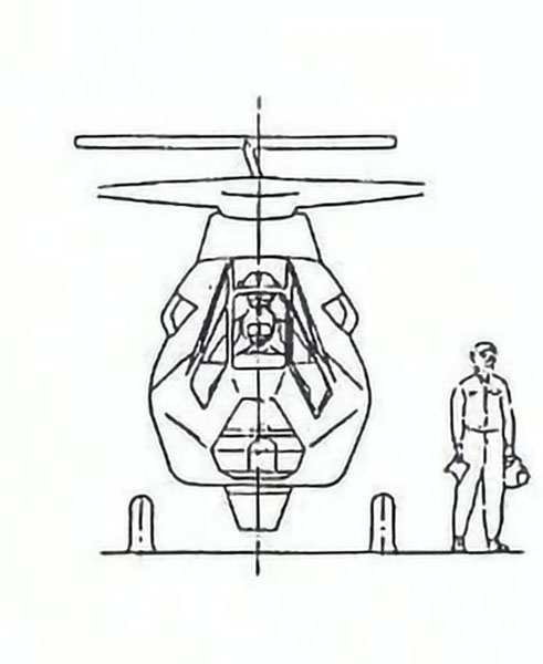
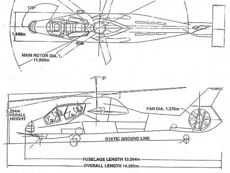
General Arrangement
Characteristics and Performance
The following data describes the LH as it was proposed in August, 1990:
Requirement
First Team Design
Primary Mission Gross Weight
10,088 lb
Alternate Maximum Gross Weight
12,813 lb
Empty Weight
7,500 lb
7,499 lb
Rotor Diameter
39.0 ft
Number of blades
5
Blade Chord
15 in
Dash Speed
≥170 knots
177 knots
Vertical Rate of Climb
≥500 ft/min
1225 ft/min
Load Factor
+3.5g
+3.5; – 1.0g
Hover Turn to Target
5 sec
4.6 sec
Masking
≤2 sec
1.6 sec
Constant Altitude 90º Turn
≤ 6 sec
5.5 sec
0 to 85 knots Accelerating Turn
≤12 sec.
11.7 sec
Other Related Programs
Shadow
To develop and demonstrate LHX advanced flight control concepts, Sikorsky modified an S-76 helicopter with a single pilot cockpit grafted on to the front of the aircraft. This was named Shadow. The aircraft had a four axis side arm controller – pitch, roll, yaw, and collective – in place of conventional cyclic and collective control sticks and pedals. The system was full fly-by-wire with safety pilots in the aft seats to monitor the tests and take over control of the aircraft if necessary.
S-76 Shadow
The Shadow was used to develop nap-of-the-earth flight control laws to reduce pilot workload and for evaluation and testing of the Night Vision Pilotage System. 60 hours of development flight tests were conducted.
In an interesting experiment it had been found that experienced pilots did have issues with transitioning to this new control concept. So a number of non-pilots were tested with the new system. They took to the system much easier. The conclusion was that young army pilots, with experience with video games and electronic controllers, could pick up the system with little problems.
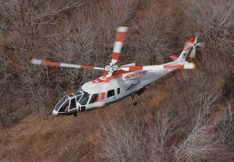
S-76 Fantail
Early on the Boeing Sikorsky team decided to use a fan-in-fin anti-torque system. Sikorsky had some prototype experience with a fan on the S-67 demo helicopter several years previously but decided it was necessary to conduct a risk reduction prototype program to get some LHX specific performance, acoustics, and handling qualities data and to get more experience with the build and integration concerns. The test vehicle chosen was an S-76B.
S-76B Fantail demo aircraft
The time from decision to the first demonstration flight was accomplished in a remarkable short 18 months. Flight testing took only six weeks, and included a full maneuver envelope. These included +2.5 g pullouts, -.5g pushovers and roll maneuvers in both directions. It also demonstrated an acoustic signature 15 dB below that of the baseline S-76.
Aviation Week and Space Technology flight tested the aircraft and reported the results in the August 27, 1990 issue. They reported that at startup the low noise was obvious, as was the absence of medium-frequency vibrations associated with conventional tail rotors. In flight a maximum yaw rate of 100 deg. per sec was achieved. They also did numerous timed yaw maneuvers against the Army’s requirements and the aircraft accomplished them all within the required times. Sideward flight was demonstrated to 70 kt. right and 65 kt. left. They commented on the lack of roll-yaw coupling, due to the fan being located lower than a conventional tail rotor.
Quoting the pilot; “The most impressive capability was the aircraft’s unlimited yaw pointing ability at speeds up to 80 kt. Flying down the runway at about 20 ft. altitude, I applied full left pedal and adjusted the cyclic control to maintain ground track. I was able to point the nose of the aircraft to any direction at will.
“Following our maneuvers on the runway, we climbed to 1,500 ft. to evaluate the yaw pointing characteristics in out-of-ground-effect flight. One of the LH maneuvers we performed was the coordinated 90 deg. turn to target at a constant airspeed and altitude. LH requirements specify the turn be completed in less than 6 sec. This maneuver would be used to quickly bring the aircraft into firing position after identifying a threat at its 90 deg. position. The conventional maneuver is a steeply banked turn to target, and we were able to execute this turn in 3.32 sec. However, using the Fantail’s unrestricted yaw capability, we made a turn using only the antitorque pedals in 2.28 sec. The 1-sec. advantage would be of significant value in an air-to-air combat situation.”
And in conclusion the article said:
“The Fantail far exceeds the abilities of conventional tail rotors in several respects, and many of the maneuvers the system is capable of do not yet exist in combat flying doctrine.”
Summary and Conclusions
In 1985, the U.S. Army initiated the LHX program. The development eventually extended to over 18 years. The program was slowed by numerous Army reductions in funding and expansions in the requirements. Through five program restructures the original date for low rate initial production in 1996 was extended to 2007.
Despite the challenges the development and flight test programs were generally successful. There were no major flight test incidents, and the basic aircraft met or exceeded all operational objectives. Forward flight speeds in excess of 200 knots were achieved, and the aircraft exhibited astonishing capabilities in sideward and rearward flight. The aircraft was extremely agile, yet it was easy to control, thanks to the advanced, tunable, characteristics of the fly-by-wire control system.
On February 22, 2004, the Department of Defense announced that it was terminating the Comanche program. Even at this time Army Lt. Gen Richard A. Cody, Army deputy chief of staff, said “. . . this team… built a tremendous aircraft. It is the most flexible, most agile aircraft that we have produced in this country… Tremendous flying characteristics and leap-ahead technology that’s going to help us as we move forward.”
Numerous reasons were given for the cancellation. Primarily it was said to be a budget issue. The expanding wars in Iraq and Afghanistan were reducing the Army’s ability to fund development programs. The Comanche’s low observable attributes, although still worthwhile, did not seem so important in 2002. The AH-64 Apache was given many of the Comanche’s MEP capabilities. And the final program restructure which extended the Initial Operational Capability date to 2008 and full fielding to 2009 didn’t help.
The Comanche was the Army’s only new helicopter program in over 20 years. With the ability to “see without being seen”, it was meant to be a game-changer on the battlefield. Now it was cancelled. Although it was restructured four times within its 18 years for funding issues, the program generally enjoyed strong support at the most senior levels of the Army and DoD — until it didn’t.