Background
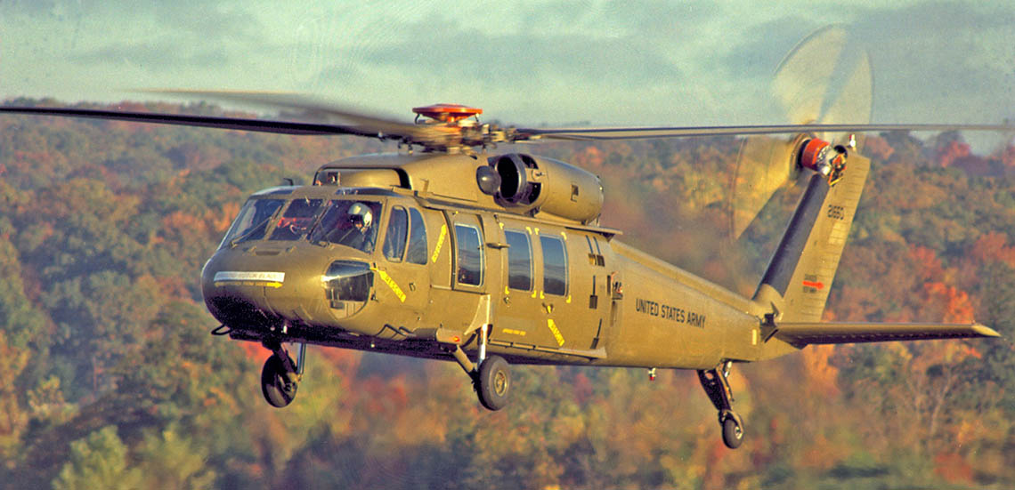
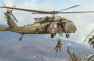
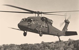
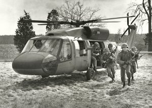
The YUH-60A was the prototype model of the UH-60A Black Hawk utility helicopter, designed and developed by Sikorsky Aircraft for the U.S. Army during the period from August 1972 through December 1976. During the preceding decade, the Army recognized the need for a new utility transport helicopter and began to draft its specification basing it strongly on the lessons learned during the war in Vietnam. At the same time, the Army initiated development of a new turbine engine matched to the performance requirements of its planned new helicopter. This new helicopter was to become the prime carrier of the Army’s 11-man rifle squad with the additional missions of evacuating wounded personnel and of resupplying troops in battle.
The Bell UH-1 Huey helicopter performed those critical missions all during the Vietnam War although it was not designed to operate in the high temperature and intense ground gunfire environment to which it was exposed. As that war wound down, the Army began a program to replace the Huey with an all-new helicopter designed to correct significant performance and survivability shortcomings experienced with all prior generation helicopters.
The focus of this new helicopter, named the Utility Tactical Transport Aircraft System (UTTAS), was on performance at hot temperature and high altitude conditions and on survivability and durability. In addition the Army required the UTTAS to be easily air transportable with essentially no disassembly needed to fit inside U.S. Air Force transports of that period, particularly the C-130 and C-141 models. This air transport requirement turned out to have a major impact on the UTTAS design as well as creating significant technical problems that shaped the course of its development.
The Army released its specification to industry for the UTTAS as part of its Request for Proposals (RFP) in January 1972. Its procurement strategy was to select two companies from those who submitted proposals, to each design and develop prototype helicopters to the same specification and using the same engine models. The two prototypes would then undergo a competitive flight evaluation by Army personnel. Selection of a winner for sole-source production would be made based on the results of that competitive fly off. When the RFP was released, the Army’s basis-of-need document established a total requirement of 1,107 aircraft however that quantity was later significantly increased during the production period as the Black Hawk’s versatility began to be understood.
The companies who responded to this RFP were Bell, Boeing-Vertol and Sikorsky. All three bidders were instructed to use two General Electric T700-GE-700 turbine engines developed by the Army specifically for the UTTAS. This engine development was also a competitive hardware evaluation with GE finally selected over the Pratt and Whitney engine. Both engines had similar configurations with axial low-pressure and centrifugal high-pressure compressors, cooled axial gas generator turbines and with front power output shafts. Both had a nominal rating of 1,500 horsepower intermediate rated power at sea level standard conditions.
In August 1972, the Army selected Sikorsky and Boeing-Vertol to design and develop their UTTAS versions designated respectively as the YUH-60A and the YUH-61A. The key performance requirements included a vertical rate of climb of at least 450 feet per minute at a 4,000-foot altitude and at 95 degrees F temperature and a cruise speed of at least 145 knots. Maneuverability requirements included achieving a yaw rate of 15 degrees per second while flying 35 knots sideways. The useful load included a crew of three plus the 11-man rifle squad and fuel for 2.3 hours of endurance with reserves.
For the first time in the history of helicopter development, stringent requirements were placed on the UTTAS design for ballistic and crash survivability. Crashworthiness characteristics later became standard requirements for US military helicopters resulting in fewer crew and occupant fatalities and injuries during both wartime and peacetime operations. In particular, occurrences of post-crash fires were dramatically reduced as a result of new design features incorporated in the design of new helicopters.
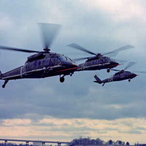
Sikorsky’s YUH-60A, designated by the company as the S-70, achieved first flight 26 months after contract award at its Stratford Connecticut facility where it was designed and built. The value of that cost-type contract in then-year dollars was $61.9 million and included construction of three fight aircraft, one ground test aircraft and one static test aircraft while the Boeing Vertol contract was for $91 million for essentially the same deliverable products. The actual contract expenditures were approximately 50% higher for both companies due to unplanned work to correct problems uncovered during flight-testing.
Configuration Features
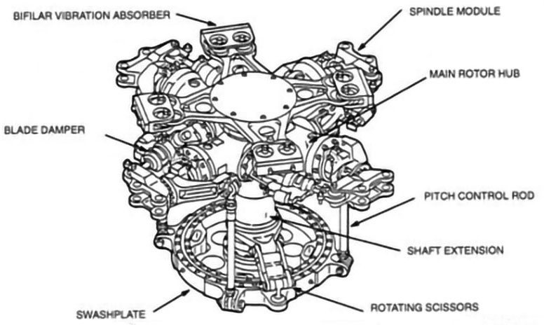
The most significant design and technology innovations of the YUH-60A were its titanium spar main rotor blades having a high lift, cambered airfoil (SC1095 and SC1094R8 airfoil sections), 18 degrees of negative twist and 20 degree aft swept tips. This combination of aerodynamic features resulted in the most efficient rotor ever produced by Sikorsky to that time. The aerodynamic efficiency of the YUH-60A main rotor, as expressed by its Figure of Merit was 0.75. A four-blade elastomeric bearing main rotor head, enclosed in a propeller-shaped hub, provided full main rotor blade articulation.
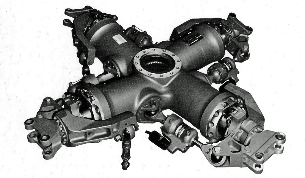
contained within the titanium hub structure.
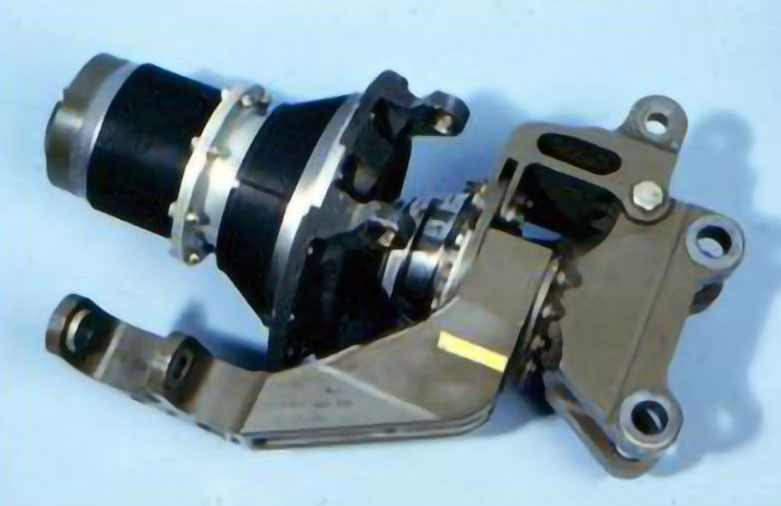
The Sikorsky UTTAS was designed with its 4-blade tail rotor canted upwards 20 degrees to provide approximately 400 pounds of extra lift. This lift at the tail permitted the aircraft center of gravity to be placed aft of the main rotor, which allowed the nose and cockpit to be moved aft thereby shortening the fuselage length to better fit inside the C-130 cabin during air transport. The added lift contributed by the canted tail rotor was provided at very low power the further helped improve the overall Figure of Merit of the aircraft. The canted tail rotor thrust resulted in yaw-to-pitch coupling that was resolved by incorporating appropriate counter coupling in the flight controls mixing unit
The crossbeam tail rotor was designed with composite materials such that no bearings were needed to provide pitch blade change. It consisted of two continuous paddles each 11 feet long mounted at 90 degrees to each other with a central hole through which passed the pitch control members
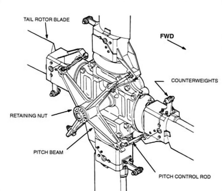

The layout of its propulsion system and in particular its modular main transmission was a unique design feature of the YUH-60A
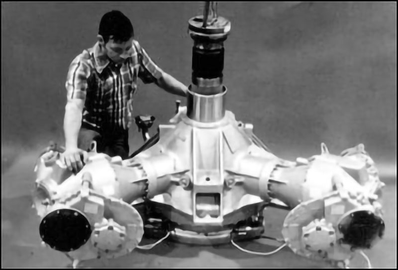
gearing stages; two bevel stages and one planetary stage. The two accessory modules that
powered hydraulic pumps and electrical generators were interchangeable left-to-right as were
the two input modules that contained the first bevel gear mesh.
Both the main and tail rotor blades were equipped with electro-thermal blankets that were embedded in their skins along the leading edges to prevent buildup of ice during flight in moderate icing conditions. These blankets were electrically pulsed to periodically melt the bond between the accreted ice and the blade skin.
The initial Stability Augmentation System (SAS) chosen for Sikorsky’s UTTAS featured fluidic technology developed by the Honeywell Company. It provided basic rate stabilization of the aircraft without any moving parts and without the need for electrical power. This fluidic SAS was the baseline system during the YUH-60A flight test and evaluation periods. However it was replaced by an electronic system, providing many more features, during early production as described in the S-70A UH-60A Black Hawk section of this website.
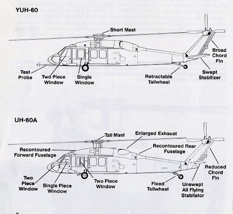
The most distinguishing configuration feature of the Sikorsky prototype included placement of its main rotor much closer to the fuselage than was normal in order to achieve a low height to facilitate fitting into the fuselages of either a C-130 or C-141 for air transport. This feature turned out to greatly increase vibrations of the YUH-60A and had to be changed.
The main rotor was raised in 1975 during the flight development period by 15 inches, which substantially corrected the vibrations problem. It was raised by adding a removable shaft extender which, when removed for air transport, allowed the rotor to be lowered to the original low position.
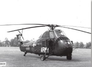
Other configuration features included a tail landing gear and a tail rotor placement on the starboard side that functioned as a tractor tail rotor as opposed to the conventional pusher tail rotor. The canted tractor tail rotor provided additional clearance and safety for ground personnel. A tail landing gear configuration was selected over a nose wheel arrangement to provide protection to the airframe during high flare landings. Sikorsky had used the tail landing gear design for its earlier S-58 (H-34) model that was well accepted by pilots.
Many features were designed into the UTTAS to enhance survivability from ground-based gunfire and heat seeking missiles and to provide occupant protection in the event of a crash. Design innovations were incorporated to greatly reduce the possibility of post-crash fires, which had been a major cause of injuries and fatalities in earlier helicopters. The sketches below illustrate the most noteworthy ballistic and crash survivability features of the UTTAS. These design features were retained and many were improved upon in follow-on production Black Hawk models.
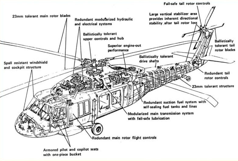
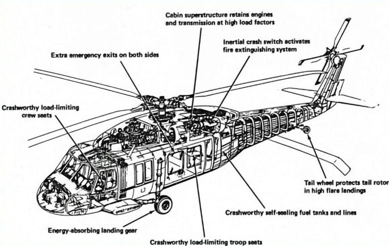
This drawing points out the most important design features to prevent post-crash fires and to protect crew and cabin occupants in the event of ground impact.
The last major feature was a fixed-incidence horizontal stabilizer having an area large enough to provide adequate longitudinal stability to compensate for the aft CG placement described above. However its unusually large area resulted in undesirable flying qualities during landing approaches and quick stop maneuvers caused by main rotor downwash impinging on the horizontal tail surface.
This downwash impingement forced an extreme nose-up attitude that caused the pilots to lose forward visibility during landings. Because of this problem, the large stabilizer was changed to a variable incidence stabilator early in the flight test program, which corrected this problem. The incidence changes were made by a full electronic system consisting of redundant electric actuators, sensors and computer systems. Stabilator incidence responds to changes in airspeed, collective stick position, aircraft pitch rate and aircraft lateral acceleration. The pilots have manual override capability by means of slew switches mounted on the cyclic sticks. The stabilator also provided many other handling qualities benefits during both cruise and maneuver flight conditions. This system has been embodied in all production Black Hawks and their derivative models to the present time.
Several other configuration changes were made to improve speed and maneuverability, including reshaping the main rotor pylon together with many changes to reduce airframe aerodynamic drag. The improved pylon shape also reduced tail shake caused by the tail rotor’s reaction to turbulent airflow coming from the main rotor pylon area.
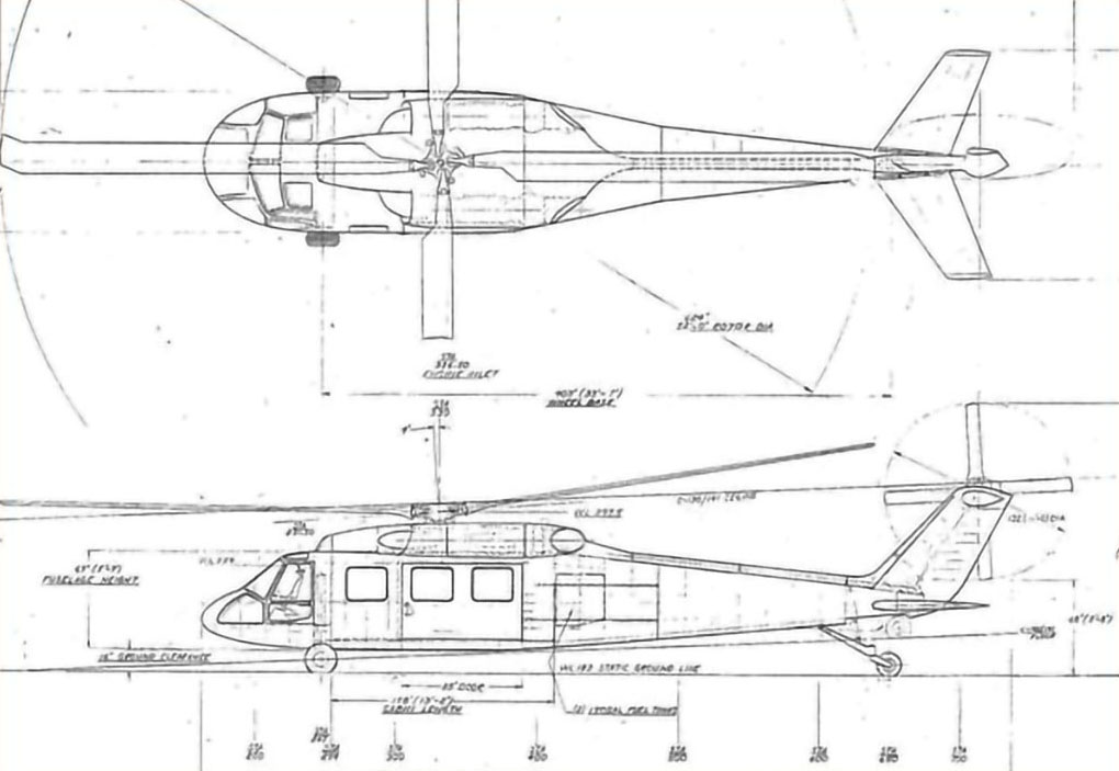
General Arrangement Drawing
Mission Systems
The major focus of the UTTAS prototype program was on design and development of the basic air vehicle for the air assault mission. Minimum work was performed relative to mission systems other than installation of the M60 window-mounted gun and development of the rotor deice system. After the production contract was awarded, work began on specific mission systems including a 6-patient litter support system; an external stores support system and electronic systems for all-weather flight as well as navigation and communication system improvements.
General Characteristics and Performance
Key parameters of the YUH-60A in December 1976 when it was selected for production by the Army were as follows:
- Main rotor diameter 53ft 8in. with four blades, chord of 1.73ft., airfoil SC1095 and SC1094R8.
- Main rotor equivalent flapping hinge offset of 15 in. (4.7% rotor radius).
- Main rotor blade twist minus 18 degrees. Rotor solidity .083. Blade area 183.5 sq. ft., Disc area 2,206 sq. ft. Tip speed 725 fps. Figure of Merit of 0.746.
- Tail rotor diameter 11 ft. with four blades, chord of 0.81ft., airfoil SC1095.
- Tail rotor blade twist minus 18 degrees, rotor solidity of .1875, blade area 17.82 sq. ft., disc area 95.04 sq. ft., tip speed 699 fps. Figure of Merit of 0.74.
- Main gearbox design power of 2,828 HP, engine speed of 20,000 rpm, main rotor speed of 258 rpm, tail rotor speed of 1,214 rpm.
- Aircraft gross weight of 16,750 lbs. and weight empty of 11,182 lbs. (at the start of Army testing in March 1976).
- Vertical rate of climb of 450 fpm at 4,000 ft. 95 degrees.
- Cruise speed of 147 knots at 4,000 ft. 95 degrees.
- Flight endurance 2.3 hours with 1,829 lbs. fuel, crew of 3 and 11-man rifle squad
- Pull-up load factor of 1.75g (held for 3 sec), push over load factor of 0g.
- Structural design load factor of 3.5.
Production History
There was no production of the YUH-60A as it was intended to serve only as a prototype with three built for flight testing, one built for ground testing and one built for laboratory structural testing. Sikorsky built a fourth flight unit concurrently with internal funding to conduct research testing and to perform marketing demonstrations.
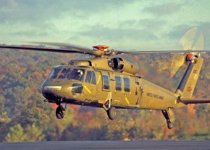
The YUH-60A design was selected by the Army over the Boeing-Vertol YUH-61A after eight months of intensive development and operational flight testing that totaled over 800 hours of flying for the three prototypes delivered by each company. On December 23, 1976, Sikorsky was awarded a sole-source contract for initial rate production of the UH-60A, which shortly after was renamed by the Army as the Black Hawk. This followed the Army’s tradition of naming its helicopters after famous Native Americans. Production information of the Black Hawk can be found in the Sikorsky Product History files under S-70 UH-60A.
Related Models
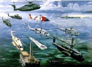
Soon after the YUH-60A design was selected by the Army to become the production UH-60A Black Hawk, the U.S. Navy and Sikorsky Aircraft began development of a ship-based model named the Seahawk. During the following years, many derivative models and variants of both the UH-60A and SH-60B were created for all branches of the U.S. Military, many of which are shown on “The Hawk Family” chart.
After a long production run of nearly 1,000 units, the Army phased out the UH-60A in favor of the improved UH-60L for its primary troop assault mission as well as for MEDEVAC missions. In turn, the UH-60L was replaced by the UH-60M also after a production run of approximately 1,000 units. Many other specialized versions of the basic UH-60 model were developed for the Army, the Air Force and for foreign military organizations. Similarly, the SH-60B Seahawk resulted in a long succession of Navy, Marine and Coast Guard models as well as those adapted to the needs of many foreign navies.
The Buckley Years – Making More Sikorsky Aircraft
From the time Eugene Buckley joined Sikorsky Aircraft in 1976 to mass-produce the Black Hawk until his retirement as president in 1999, Buckley oversaw delivery of some 3,200 helicopters.
Sikorsky Takes the UTTAS Prize
The first flight of Sikorsky Aircraft’s Black Hawk occurred 50 years ago, on October 17, 1974. Since then, over 5000 Black Hawks have been delivered to customers, making it Sikorsky’s longest production program.
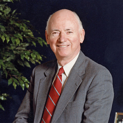
Bill Paul: Reflections on Sikorsky’s 100th Anniversary
Former Sikorsky President Bill Paul reflects on his career with Sikorsky, meeting Igor Sikorsky, and the Sikorsky Aircraft Company’s 100th anniversary.
Sikorsky Lifts the Army
The U.S. Army saw the possibilities of the helicopter early in its development, thus beginning a relationship with Sikorsky Aircraft that continues to this day.
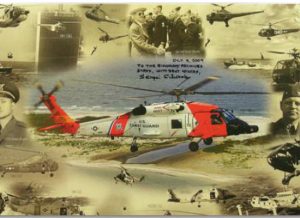
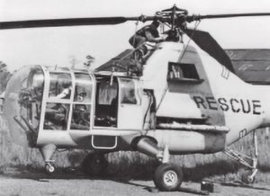
Sikorsky Serves the Coast Guard
A flight demonstration of Igor Sikorsky’s VS-300A helicopter at Bridgeport, Connecticut in April 1942 started an air-sea rescue revolution in the U.S. Coast Guard.
Bill Paul: Management Contributions to the Black Hawk Helicopter’s Success
Bill Paul recollects one of the key milestones of Sikorsky history, the win of the UTTAS program that became the Black Hawk helicopter.
Ray Leoni: Recollections of a Sikorsky Junior Engineer
Ray Leoni recollects his 41-year career at Sikorsky Aircraft, beginning as a junior engineer and retiring as a Senior VP of Engineering and Advanced Programs.
Evolution of the Armed Helicopter
Military users quickly understood the flexibility and fire-power of rotary wing platforms and ultimately evolved highly integrated weapons systems ready to protect themselves and others.
The Sikorsky Black Hawk in U.S. Military Service
When Black Hawk program manager Colonel Richard Kenyon received keys to Sikorsky’s first production UH-60A on October 31, 1978, the U.S. Army received the powerful, hardened assault helicopter it wanted.
Sikorsky Helicopters in U.S. Air Force Rescue Squadrons
The HH-60W Combat Rescue Helicopter is the latest in the life-saving line of Sikorsky helicopters made for U.S. Air Force Rescue Squadrons. The Whiskey will round out a century of vertical flight rescue heroism.
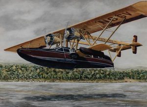
Sikorsky Aircraft Color Schemes
This issue of the newsletter illustrates some of the artistic variations in the exterior color schemes of aircraft delivered during Igor Sikorsky’s three careers.
Sikorsky Aircraft Paintings by Andy Whyte
This issue of the newsletter is devoted to the aircraft designs and paintings by Andy Whyte, who had a 40 year career at Sikorsky Aircraft.