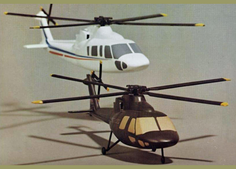
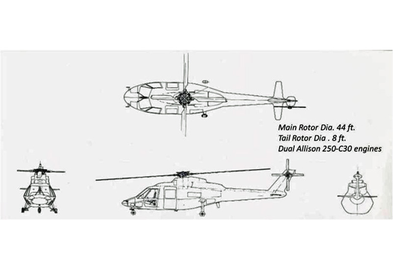
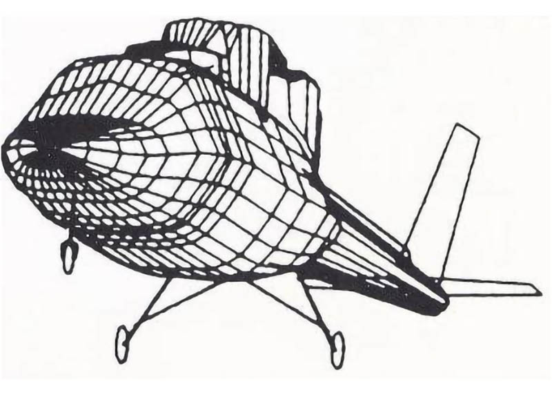
Under contract to the U.S. Army Applied Technology Laboratory, USARTL (AVRADCOM), Sikorsky Aircraft conducted an Advanced Composite Airframe Program (ACAP) to demonstrate the weight and cost saving potential of advanced composite materials when used to the maximum extent practical in a helicopter airframe designed to meet stringent military requirements. Initial preliminary design study contracts were conducted by Sikorsky, Bell Helicopter, Boeing-Vertol, Hughes, and Kaman between September 1979 and May 1980. At that point in time, composite material applications were primarily limited to secondary structures such as control surfaces, fairings, and doors, but no primary airframe structures. Following the preliminary design studies, two subsequent contracts were awarded to Bell Helicopter, and Sikorsky Aircraft to design, build, test, and fly technology demonstrators. The Sikorsky demonstrator was designated the S-75 which was a derivative of the S-76 commercial helicopter. The S-75 used the dynamic system (engines, rotors, transmissions, and flight controls) from the S-76.
The design of the Sikorsky S-75 (lower) was derived from the S-76 (upper).
Extensive sub-component risk reduction development tests were conducted to support the design, followed by fabrication of a tool proof article, a static test article, and a flight vehicle. The entire program was completed in 5 years for $29M.
Preliminary Design
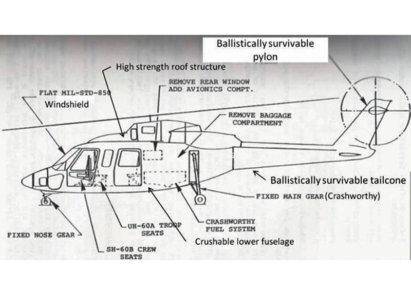
Preliminary design studies for the S-75 started with creation of a militarized S-76 helicopter, based on current state of the art construction, i.e. predominantly metal for the primary structure.
Militarized S-76 Baseline features
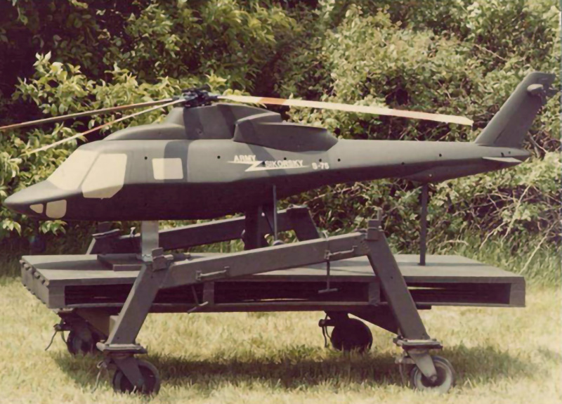
S-75 Wind tunnel model
Three variant preliminary designs were then synthesized, optimized respectively for maximum weight savings, low radar detectability, and ballistic survivability. A final concept representing a balanced optimization of all attributes was then created. The wind tunnel model was tested in the United Technologies Research Center to evaluate the aerodynamic effects of the shaped fuselage and fixed landing gear.
Major program objectives included a 22% weight saving, 17% manufacturing cost saving, and 20% operational cost reduction compared to a militarized metal baseline helicopter.
Attribute
Objective
Gross Weight
8470 lb
Primary Mission
Two fully equipped troops @ 2,000 ft. alt., 95˚F for 2.3 hours
Alternate Mission
6 troops @ sea level standard
Ballistic Tolerance
Minimize vulnerable area to specified solid round and explosive incendiary threats
Crashworthiness
MIL-STD-1290
Radar Cross Section
15 db reduction from metal baseline
Advanced Avionics, targeting system
Space, weight, and power
General Description
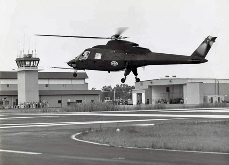
The first flight of the Sikorsky S-75 was on August 16, 1984 at the Sikorsky West Palm Beach Flight Test Center. It flew over one year ahead of the competing Bell D-292 ACAP helicopter.
S-75 First flight at Sikorsky West Palm Beach Flight Test Facility
S-75 Three-View Drawing
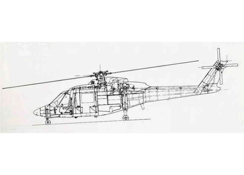
S-75 Inboard profile
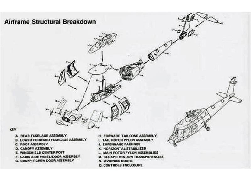
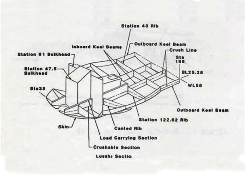
S-75 Airframe Structural Breakdown
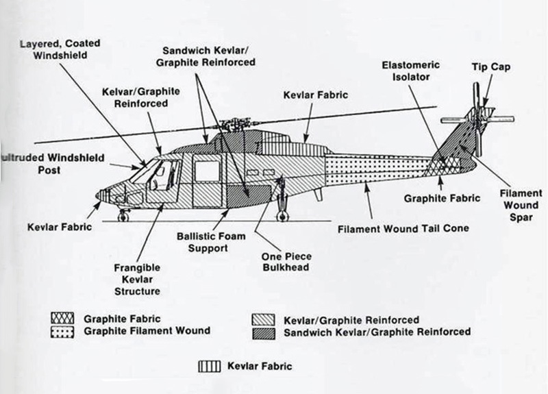
S-75 Airframe Materials
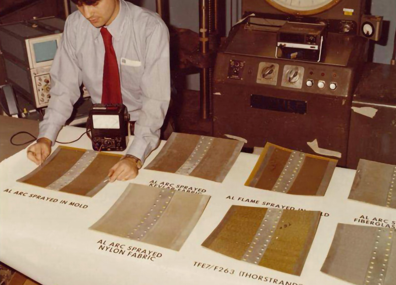
Conductive coating system evaluations
Extensive tradeoffs were conducted to optimize the design and manufacturing process for each section of the fuselage. As a result, the fuselage is comprised of a broad range of novel design concepts and manufacturing processes. The unique features of these major subcomponents will be discussed in subsequent sections.
Primary structural materials were graphite epoxy, Kevlar epoxy, and Nomex and aluminum honeycombs. The graphite epoxy came in uni-directional and woven forms and used a low flow Narmco 5240 resin system. The low flow resin system eliminated the need for difficult bleeding control means associated with earlier low-viscosity resin systems. Other materials included Rohacell foam in the tailcone stringers, ballistic foam to support the fuel tanks, and aluminum mesh for lightning strike protection. The airframe weight was 82% composite material. Metal components were limited to the fire resistant engine decks, firewalls, small fittings, brackets, and hardware. Material properties were obtained from Sikorsky data bases, suppliers, and special characterization tests as required.
A variety of conductive coating systems were evaluated for electrical properties. The conductive coatings were applied to the external skins for lightning strike protection.
Radar Cross Section Reduction
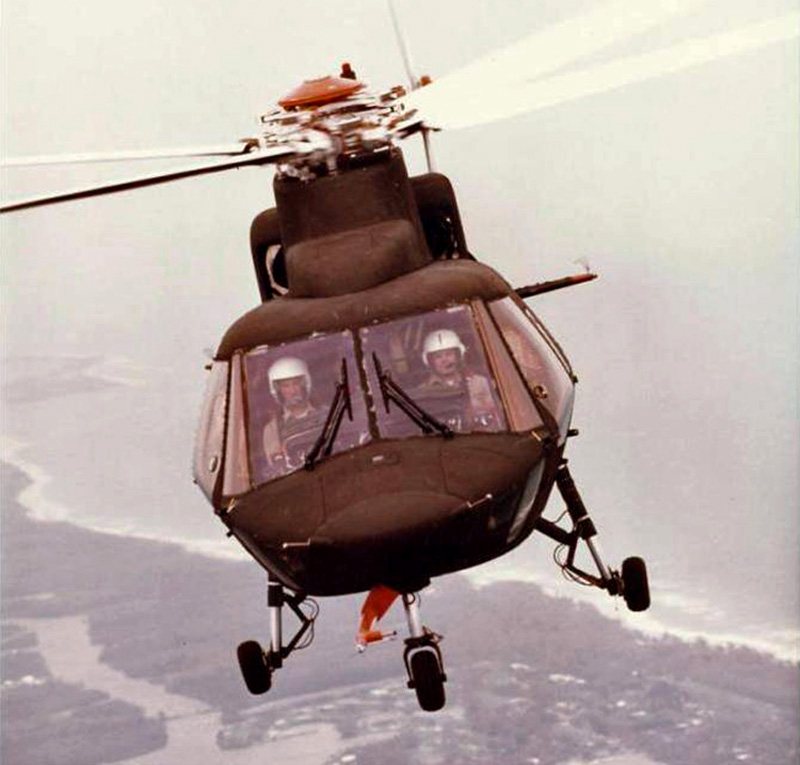
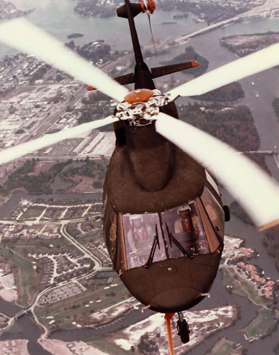
Preliminary designs were conceptualized to explore different approaches for reducing radar cross section, and to establish weight, cost, and performance, attributes. The major design considerations were fuselage shaping, and the use of radar absorbing materials. From these studies, selective features were incorporated in the final S-75 design. They included fuselage shaping, conductive coated transparencies, and selective use of radar absorbing sandwich structures. The fuselage sides were sloped and conductively coated to deflect incoming radar waves away from the transmitting receivers. Radar absorbing material applications was limited to the sides of the main rotor pylon, and vertical tail surfaces. The sloped fuselage sides are readily apparent in the head-on view of the S-75 in flight.
Head-on View of the S-75
Schedule
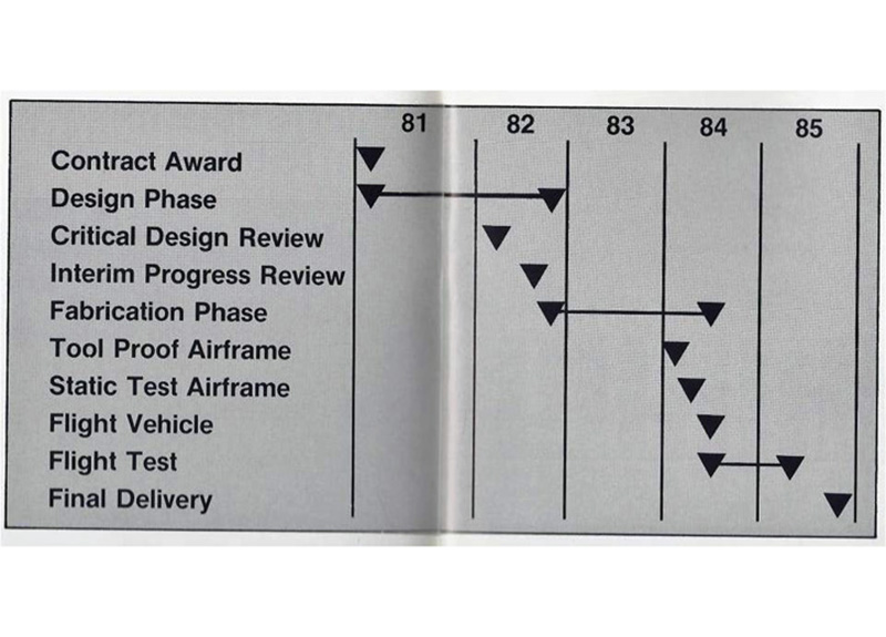
The Sikorsky S-75 ACAP had a 5 year development schedule, from contract award to final delivery of the flight test article to the Army. The program was managed by Sikorsky Aircraft with Hercules, in Salt Lake City, Utah, and Vought as major sub contractors. Hercules was responsible for fabrication of the tailcone, tail rotor pylon, and horizontal stabilizer. Vought, in Dallas Texas did the detail design, and conducted risk reduction development tests for the lower fuselage. All of the remaining major sub-components were fabricated by Sikorsky Aircraft in its composite shop in Bridgeport, Ct. Final assembly, and subsystem integration was performed in the Sikorsky Development Manufacturing Center in Stratford, Ct.
ACAP Development Schedule
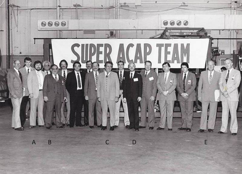
ACAP Team (A – Hugh Kearney, B- Dan Ruck, C – Bruce Kay, D – Danny Good, E – Joe Ozelsky)
Key Sikorsky personnel included; Jim Ray (Program Manager), Bruce Kay (Engineering Manager), Jim MacVicar (Chief of Design), Herb Gaebe (Structures), Joe Ozelsky (Operations Manager), Dan Ruck (Manufacturing Engineering), Hugh Kearney (Test), Sid Gurley (Project test pilot), Jack Terceno (Airframe Design), Hugh Taylor (M&P), and John Milner (RCS analysis). The Army project engineer was Danny Good. Figure S75-12 shows some of the ACAP team notables at the rollout ceremony.
Design
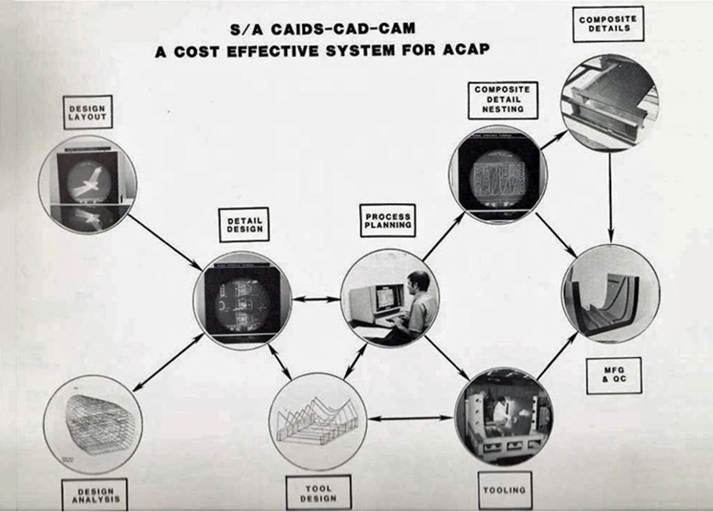
A number of specialized software programs were used for the first time at Sikorsky to design this helicopter. First, and foremost, was the use of Sikorsky’s, in-house developed, Computer Aided Interactive Design System (CAIDS) to do detail design, and manufacturing planning. This was the first time that computer-aided design was used to design a Sikorsky helicopter and its associated tooling. Previous Sikorsky helicopters were designed using ink-on-mylar drawings. By today’s standards, CAIDS was a primitive system, but it represented a major change in the way aircraft would be designed in the future. In addition to learning how to use a new computer-aided design system, the design team had to be trained in designing composites. This entailed basics such as materials, drawing formats, analysis methods, and manufacturing processes. Special training courses were created and disseminated to the design team.
Sikorsky CAIDS Applications
S-75 HELISCAT RCS Model
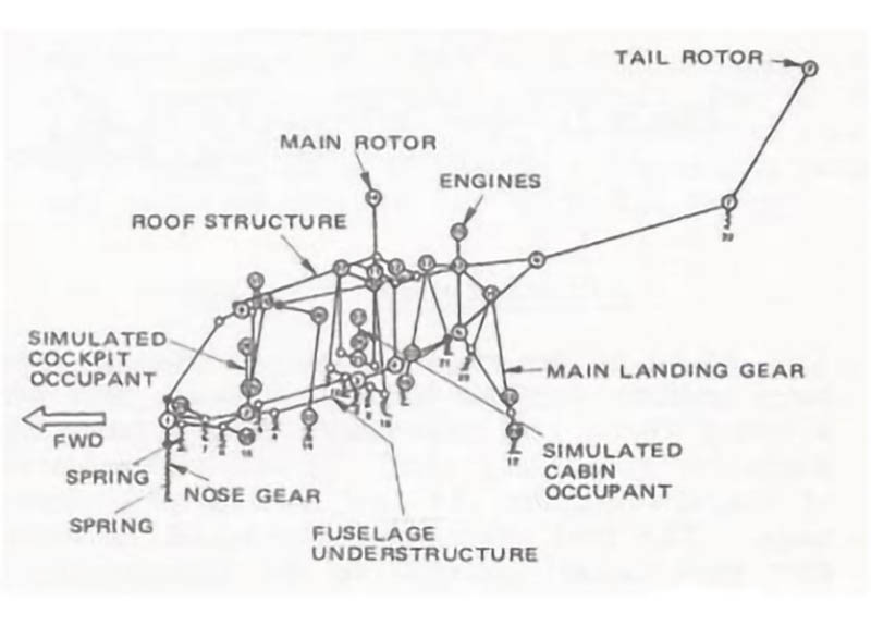
S-75 KRASH Model
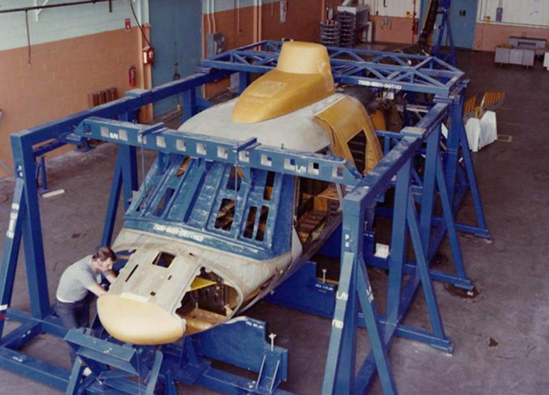
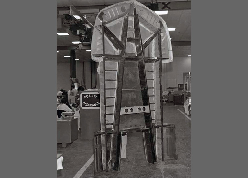
S-75 Tool Proof Article in Final Assembly Fixture
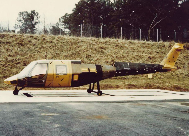
S-75 Tool Proof Article at Ballistic Test Range, Fort Eustis, Virginia
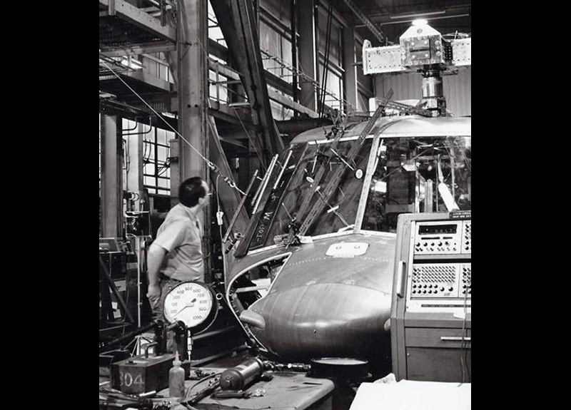
S-75 Airframe in NASA Static Test Facility in Langley, Virginia prior to conducting a windshield pressure loading test. Note the very narrow windshield post in this photograph. Further discussion of this windshield post is in the Novel Features section.
To address some of the military requirements, new software programs were acquired and implemented. The KRASH program was used to evaluate how the airframe would perform under various crash conditions. The KRASH model simulated the aircraft mass distributions, airframe stiffness, landing gear energy absorption, and fuselage crushing characteristics.
Radar signature was evaluated with physics-based models and the HELISCAT computer program, which was used to calculate the radar cross section of the S-75. Since ACAP was strictly an airframe research program, the analysis focused only on the fuselage, and neglected any radar cross-section contributions from the rotors, engines and landing gear. This was the first time that radar cross section was considered for a helicopter
Three S-75 helicopters were built: a tool proof airframe, a static test article, and a flight article. The tool proof article was used to check the tooling, and then selective areas were destructively torn down to evaluate quality. Teardown examinations consisted of cutting sections from the composite parts to examine laminate quality for defects such as porosity, voids, delaminations, fiber wrinkling, etc. Mechanical tests were also conducted on specimens to compare the “as manufactured” strength properties to design allowables. The tool proof article was then subsequently subjected to ballistic testing, which was performed at the Army’s ballistic test range in Fort Eustis, Virginia.
A full scale static test article was built to validate the structural integrity of the S-75 airframe. Structural testing is particularly important for composite structures, even today, because of the material’s highly orthotropic (directional) strength properties. Interlaminar properties are very low in comparison to in-plane properties, so any small out of plane loads, not accounted for in structural analyses can have extremely debilitating effects. The test article was subjected to critical flight and landing load conditions. In addition special testing techniques were developed to address material environmental degradation from prolonged temperature/humidity exposure. The static test article was then subjected to a controlled crash test at the NASA crash test facility at Langley, Virginia.
Risk Reduction Development Tests
Extensive risk reduction testing was conducted in parallel with the design phase. Since the ACAP was a technology demonstration program, intended to show that composite materials could perform equivalent to, or better than traditional metal structures, the risk reduction development testing was a critical step in developing and substantiating these capabilities. Some of these tests and demonstrations were necessary to understand how composites behaved under stringent military conditions, to develop techniques for satisfying those requirements, and finally to demonstrate requirement compliance. A building block test approach was used. Testing ranged from basic material characterization coupon testing, element tests, producibility demonstrations, full scale sub-component tests, and finally, aircraft ground and flight test. Some of these tests were conducted as part of a parallel Sikorsky airframe IR&D program.
Simulated fuel cell enclosure ballistic test
Novel Features
Each section of the fuselage was analyzed to comply with the military specification requirements, and then optimized for weight and manufacturing cost based on its unique geometry, applied loads, and interface requirements. What evolved was a number of very unique, novel designs, and manufacturing processes that had never been used before. The following paragraphs will discuss how each section of the airframe was designed and manufactured, starting from the nose, and running aft to the tail.
Nose Section
The nose section is the exception for not employing any advanced technology. It was simply a hand layed up composite structure, using the same type construction as its parent S-76. The structure contained an integral nose-cone frame, and molded-in recessed setbacks for the lower cockpit windows, and equipment doors.
Nose section being layed up
Windshield Post
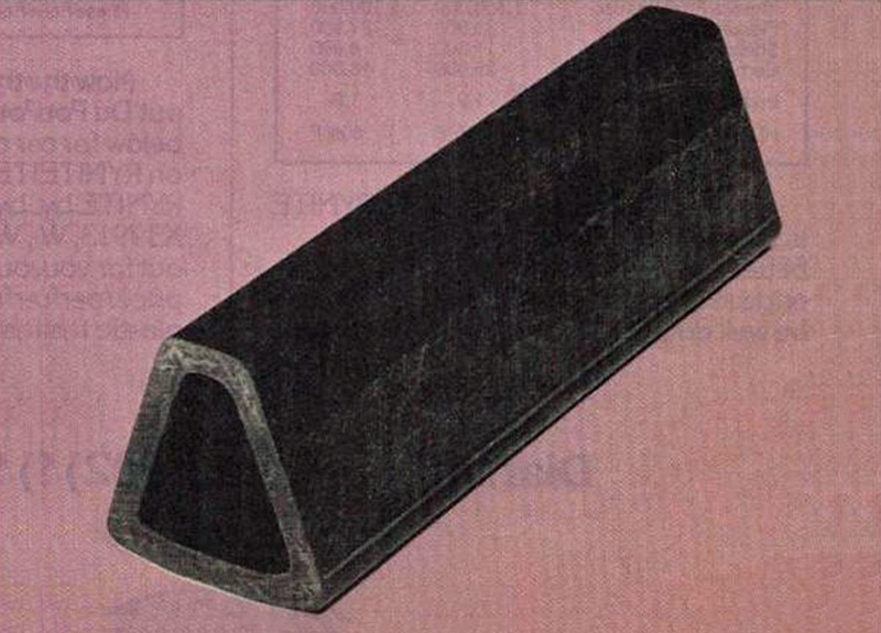
To provide unimpeded visibility for flight crews, windshield posts should not be wider than 2 inches, which is the distance between eyeballs. Anything wider than 2 inches creates a cone of widening obstruction. To meet this requirement, a narrow trapezoidal shaped, pultruded graphite post was designed and manufactured. Pultrusion is an automated manufacturing process whereby reinforcing fibers are impregnated with resin and pulled through a die, to provide long strips of material that are cut to length. It is analogous to the extrusion process for metals. The post not only had to support windshield pressure loads, but it is was also loaded in compression to hold up the cabin roof. Its material is predominantly unidirectional graphite, in a vinyl ester resin, with layers of random fiber matt intermixed to minimize splitting of the uni-material. This windshield post construction received the top award in the Aircraft/Aerospace Category at the 1983 Society of Plastics Industries’ Reinforced Plastics/Composites Institute competition held in Houston, Texas.
Pultruded Windshield Post
Lower Fuselage
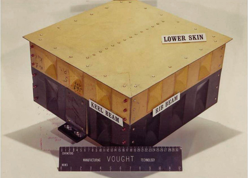
The lower fuselage was comprised of longitudinal beams, transverse frames, and a stiffened Kevlar skin. Major functional requirements include supporting the nose landing gear, crew and passenger seats, the cargo floor, and cargo tie downs. In addition the structure was designed to attenuate crash energy, by controlled crushing. Development of this unique capability will be described at the end of this section.
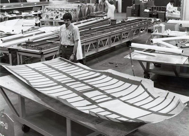
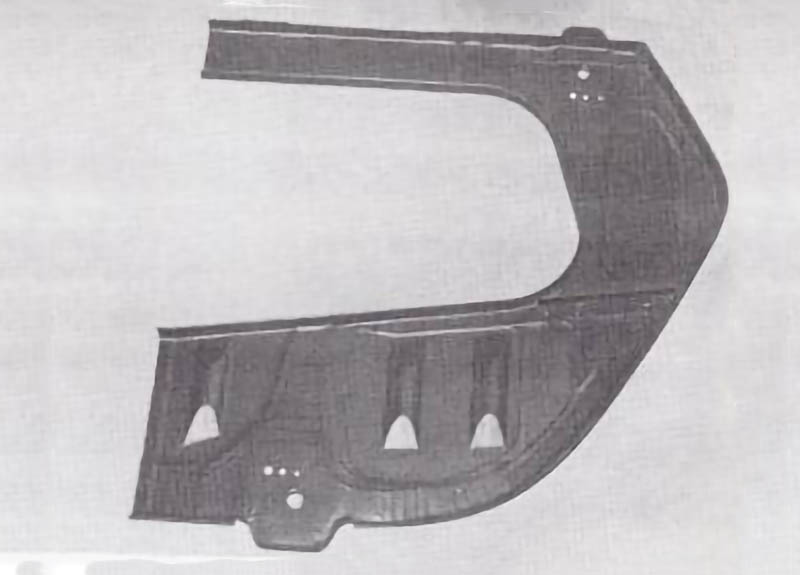
Sikorsky S-75 lower skin, with graphite caps for the beams, frames and stringers integrally cured with the skin. Composite stringers were subsequently bonded over the graphite caps
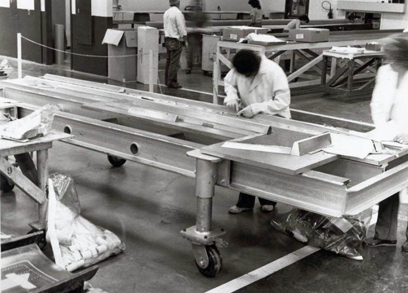
Sikorsky S-75 keel beam being layed up. The keel beams ran the length of the cabin and contained a raised reinforced section that supported the nose landing gear
Skin shear loads were relatively low, and so a post-buckled, diagonal tension design approach provided the lowest weight. Further, since Kevlar and graphite have similar tensile strengths, but Kevlar has a lower density, Kevlar was selected as the material of choice.
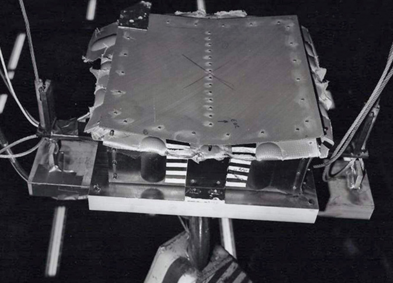
Energy-Absorbing Fuselage
Army crashworthiness design guides had previously shown that metal helicopter airframes can absorb crash energy via fuselage crushing. This capability is inherent in conventional metal airframe structures. Prior to ACAP, there were concerns that because composites, particularly graphite fibers, do not have a yield point (linear stress-strain to failure) and therefore they could not absorb energy. To alleviate this concern, several design approaches were developed to enable energy absorption. A series of tests were then conducted to quantify this capability. The energy absorption quantified by these tests was then input to the KRASH program, which was used to evaluate how the system would perform under specified combinations or roll, pitch and sink speeds.
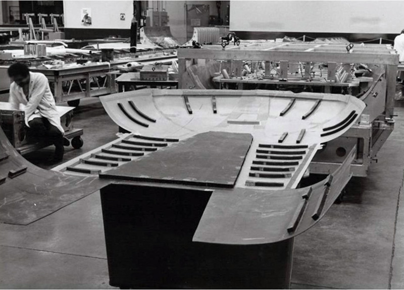
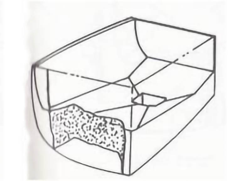
Crush test specimen representative of the Sikorsky S-75 lower fuselage structure, showing the part upside-down, containing intersecting frames and beams with a section of skin. The upper section of the frames and beams are made from high strength graphite epoxy while the lower section and skin is Kevlar epoxy.
Crushed Sikorsky S-75 lower fuselage test specimen, showing how the lower Kevlar section crushes to absorb energy while the upper graphite section remains structurally intact
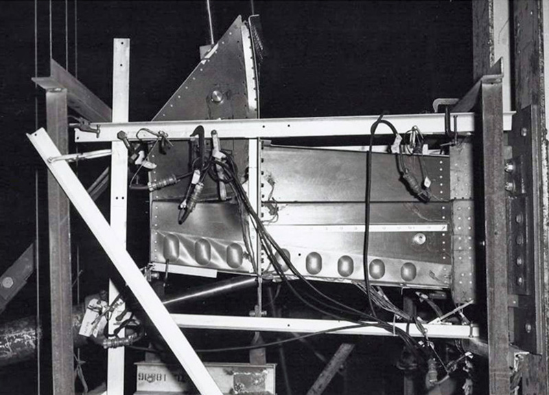
Sikorsky S-75 nose landing gear support structure subcomponent test with the keel beam structure that supports the nose landing gear under load. Diagonal tension wrinkles are readily visible in the lower beaded Kevlar skirt portion of the keel beam.
Cabin Roof
The cabin roof supports the main transmission, engines, and flight controls. Longitudinal beams contain the attachments for the main transmission that transmit flight loads from the rotor system into the airframe. This is an all-bonded assembly, something that had never been attempted for primary structures that react high fatigue loads from the rotor system.
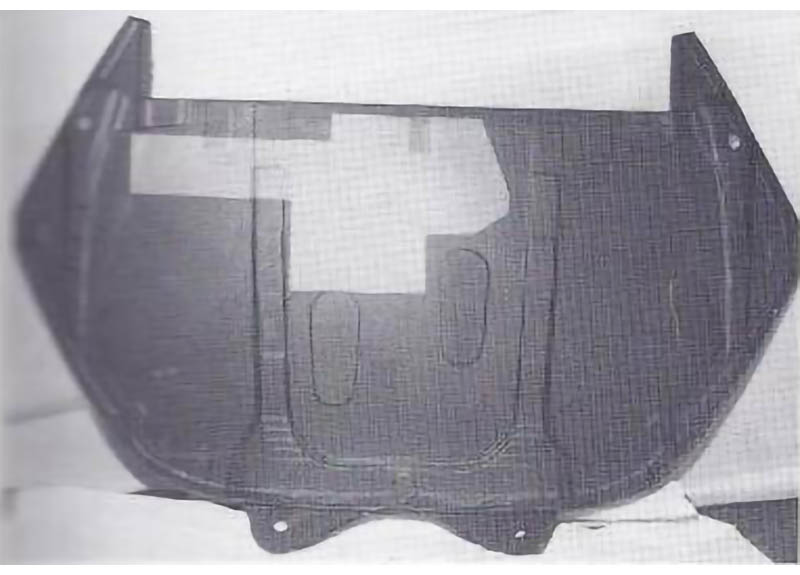
Sikorsky S-75 cabin roof skin prior to installation of frames and beams. Here, the honeycomb sandwich skin stiffeners are in plain view. Where high shear loads were present, the skin was made from graphite, which are the darker panels
Sikorsky S-75 roof bonding fixture
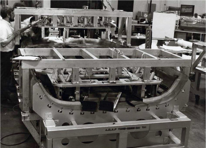
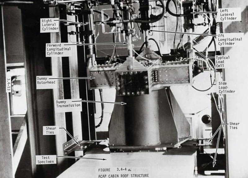
Sikorsky S-75 roof sub-component fatigue test setup, showing how rotor loads were applied to the subcomponent roof structure
Similar to the lower skin, the cabin roof skin had a post-buckled construction for lightly loaded skin panels. A section of honeycomb sandwich in the central portion of the skin was used as a mounting base for flight control servos and hydraulic equipment installed inside the main rotor pylon. The roof structure was assembled using adhesive bonding. Pressure was applied to the bond joints using mechanical pressure provided by the jig. Heat was applied by placing the entire unit in an oven.
Fatigue strength of the airframe was validated by subcomponent testing. The roof structure was statically loaded to 128% of design ultimate load. It was then subjected to 70,000 ground-air-ground (GAG) load cycles, which was equivalent to 10,000 flight hours. One of the main transmission support beams was then deliberately severed, and an additional 2,000 GAG cycles was applied. The specimen was subsequently loaded to failure, since no damage propagation occurred during the fatigue cycling. Failure occurred at 160% of design limit load which was 60% above the required load for that condition.
Main Landing Gear Support Structure
The main landing gear shock struts and drag beams are supported by a graphite frame featuring integral, molded hard points and a graphite bulkhead. The simplicity of just building up plies and then tapering them off to distribute the loads into the structure represents the most elegant structural design in the entire airframe.
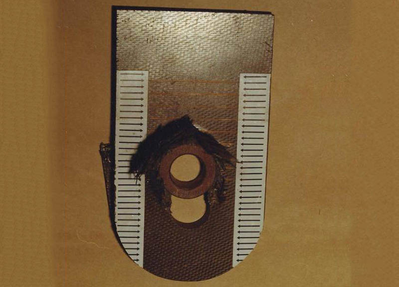
The built up lugs also featured a local crushing capability. This was accomplished by using a predominantly +/- 45˚ laminate architecture. The main purpose for this feature was the ability to accommodate some deformation of the landing gear attachments, so they would not break off prematurely while the landing gear stroked under severe crash conditions. Figure S75-35 shows the deformation obtained from a lug test specimen test.
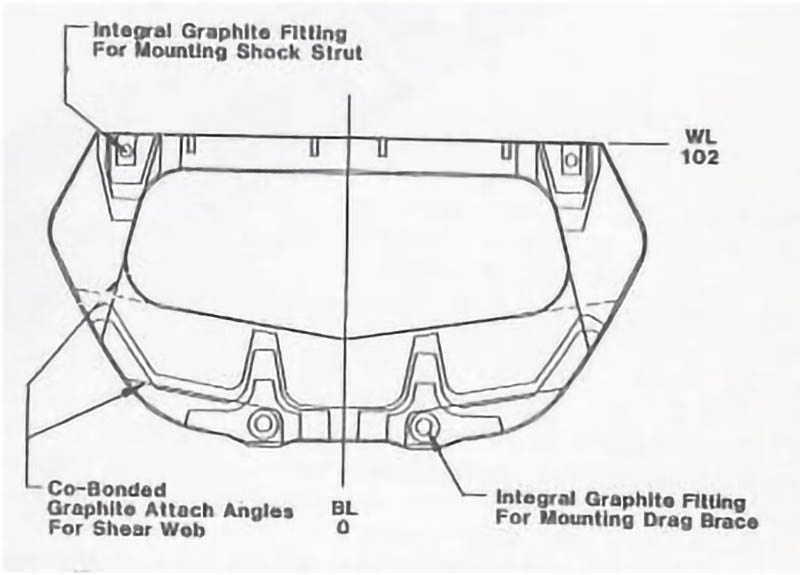
Diagram of main landing gear support frame showing the hard points molded into the frame
Half of the main landing gear support frame
Main landing gear support bulkhead
Lug crush test specimen showing the deformation obtained from a crush test
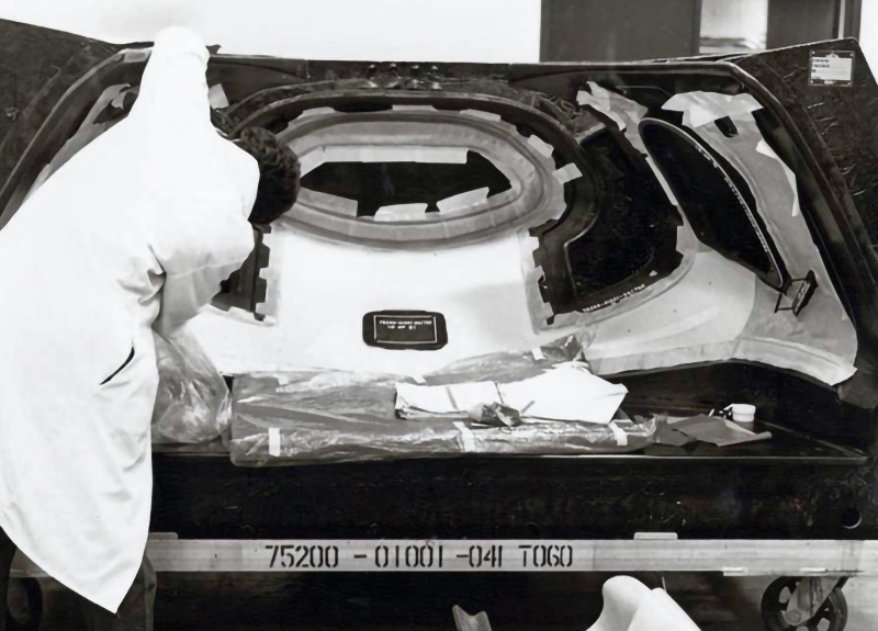
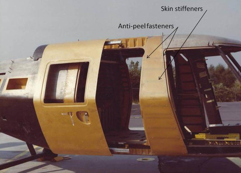
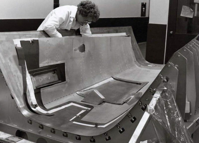
Pre-hung Doors Door fit problems have been a long standing problem for helicopters, resulting in water leakage. To remedy this problem a pre-hung approach, similar to that used on household doors, was used. The door surround structure consisted of a one piece molded unit containing a door jamb integrally molded with door frames, and skin. The molded aperture was rigid, and the unit was joined to the fuselage by fastening the flexible skin to adjacent fuselage frames. Since the skin was flexible, and the aperture was structurally isolated from the fuselage structure, fuselage assembly tolerances would not affect the door aperture. The door was also pre-fit to its aperture prior to assembling it to the fuselage. The following photograph shows how the pre-hung door assembly, shown in yellow kevlar, fastens to the cockpit door frame and aft cabin bulkhead. Also evident in this photograph are the “chicken fasteners” installed at the ends of the bonded skin stiffeners (dark stripes) to prevent peeling.
Pre-hung cargo door assembly
Rear Fuselage The rear fuselage contains the fuel cells, main landing gear and engine support structures. The basic shell structure is honeycomb sandwich, designed to react to fuel pressure loads, in addition to airframe flight and ground loads. The outboard sides of the bulkhead were beaded Kevlar, and designed to attenuate energy in lateral crash conditions. The lower section of the bulkhead was made with corrugated construction. This corrugated construction proved to be lighter than sandwich for resisting fuel pressure loads. The recesses between corrugations also provided space that was filled with fire suppressant powder to mitigate fires from incendiary threats. Chopped fiber reinforced foam blocks were used to support the fuel cells. The foam blocks avoided having any potentially combustible gasses in the ullage (space) around the fuel cells, and eliminated the need for additional structural members between the external sandwich skin, and the slab-sided fuel cells.
The rear fuselage sandwich skins were layed-up in steel shell molds. The use of steel shell molds replaced traditional fiberglass epoxy molds that were previously used for this type of components. Steel eliminated differential thermal expansion and leakage problems associated with the older molds. A removable mandrel at the bottom of the mold was used to form an integral enclosure for an external receptacle.
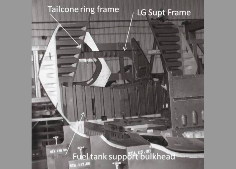
Rear fuselage primary components in the assembly jig, including the bulkhead that abuts to the fuel cell, the main landing gear support frame and the ring frame that attaches to the tailcone.
Reinforced foam fuel cell support structure consisting of chopped fiber
The rear fuselage skin shell mold was made of steel to eliminate differential thermal expansion and leakage problems.
Tailcone
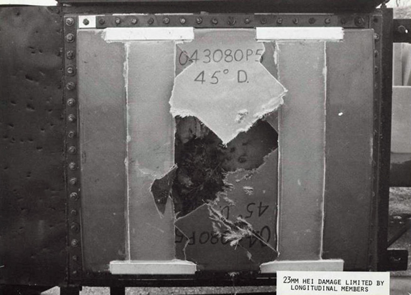
The tailcone was, by far the most challenging part to manufacture for the S-75. Aside from the normal structural and frequency placement requirements, the tailcone was designed to stringent High Explosive Incendiary (HEI) and tumbled round ballistic survivability requirements. This capability was provided by incorporating large redundant longerons and frames that could tolerate significant damage. However, to survive internal detonations of HEI threats, means to relieve internal pressures were necessary. This was accomplished by building blow-out patches into the skin. A network of doubler bands were layed up over, and extended beyond the frames and longerons onto which the skins were co-cured. Narrow grooves were then cut into the skins down to the doubler plies. Thus the skins were attached to the substructure only through the co-cured bond joint to the doubler plies. This joint was sufficient to carry skin shear loads, but would separate when subjected to out of plane pressure loads from internal explosive detonations. Sub-component testing demonstrated the viability of this concept, prior to subjecting the tool proof article to full scale ballistic tests. In addition the tailcone was designed to break off during severe crashes, to reduce the fuselage mass that the landing gear had to support.
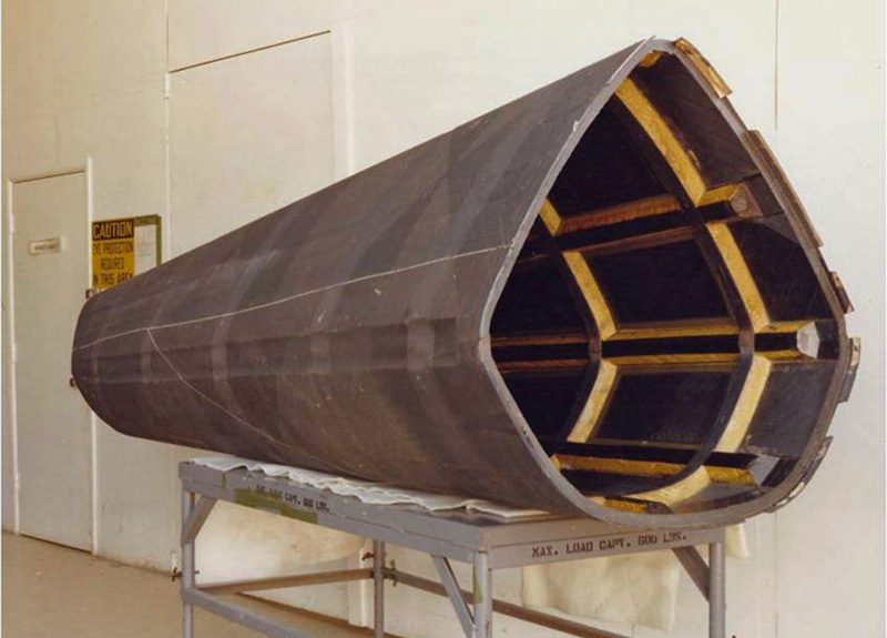
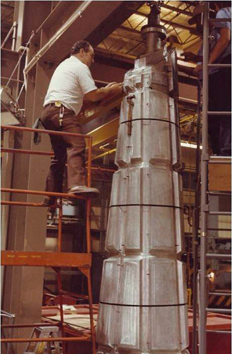
Meeting these demanding tailcone functional requirements was the easy part. Building the tailcone was the hard part. In order to meet demanding unit cost requirements, the tailcone was built as a single co-cured component, fabricated by automated filament-winding. Filament-winding ultimately evolved to fiber placement. This was the first time that filament-winding was used to build a primary structure of this complexity, with the internal structure built upon a filament-winding mandrel. The segments between frames and longerons were loose pieces that were held in place by adhesives that melted when the part was heated in the autoclave.
One-Piece Filament-Wound Tailcone Structure
A worker installing removable segments on the tailcone filament-winding mandrel. The segments were temporarily held in place by bands while the adhesive set.
The ±45˚ skins being wound over the longerons and frames on the tailcone skin filament-winding mandrel.
Some of the problems that had to be overcome included, extracting the mandrel from the structure after curing, tool mass cool down after curing, crushing of the skin over the longerons voids and gaps between the cores and longeron/frame webs, and delamination of the tailcone attach flanges. Each of these problems was addressed sequentially, and quality parts were subsequently built for the static test and flight articles. The biggest problem was to make sure that the longeron filler material would maintain pressure against the longeron/frame webs. Initially honeycomb was used as a filler material, but this was changed to Rohacell foam, which could be fitted into the cavities with a preload.
Empennage
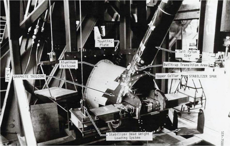
The empennage consists of the vertical fin mounting the tail rotor, and the horizontal stabilizer. Both of these components were supported by an extension of the tailcone. The main circular spar of the vertical fin was attached directly to the skin shell structure by simple collars. This eliminated the need for more complex bulkhead structural splicing. The horizontal stabilizer spar was mounted to the skin in a similar fashion, except the actual connection was through elastomeric vibration isolators.
Empennage Sub-Component Static Test
Tail Rotor Pylon
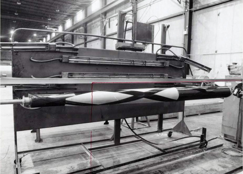
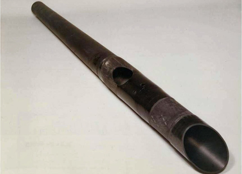
The major design drivers for the tail rotor pylon were ballistic survivability and low radar cross section. A tumbled round ballistic threat precluded the use of a conventional box beam main spar, since a single round aligned with a spar or skin could sever two beam caps, with a total loss of bending strength. The vertical fin geometry was too small to accommodate multiple, unaligned spars to defeat this type of threat. The solution was to use a round spar with enough constant circumferential thickness to withstand a ballistic gash from any direction. This capability was successfully demonstrated by inducing simulated ballistic damage in the empennage sub-component static test article. The circular cross section also provided a superior means to resist HEI overpressures by virtue of its inherent hoop tension capability. The simple shape also enhanced producibility since it could be readily layed up using automated filament winding equipment. Fiber angles were optimized for bending and torsion, which included using some non-traditional low-angle fiber architectures. Finally, the circular spar arrangement simplified the ability to accommodate airfoil shaped radar absorbent honeycomb sandwich external skins.
Filament winding tail rotor pylon spar
Completed tail rotor spar. Note the large reinforced hole to allow the tail rotor drive shaft to pass through.
Tail rotor pylon skin assembly
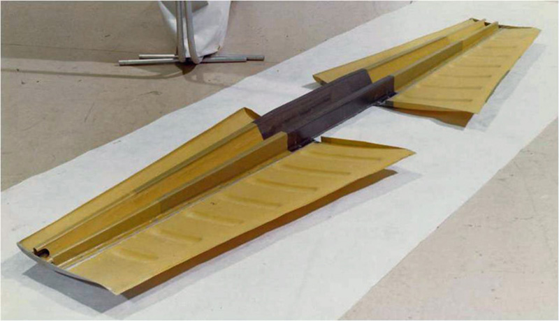
Horizontal Stabilizer
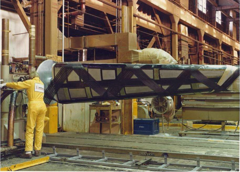
The horizontal stabilizer is a fairly simple three-piece assembly, made up from two skins and an “M” shaped spar. The “M” shaped spar eliminated the need for ribs, since the central “V” portion of the spar formed a continuous span-wise truss that was capable of reacting both bending and torsional loads. The spar was bonded to the skins and the trailing edge of the skin was beaded. This stiffened the skin sufficiently to transfer aerodynamic loads to the main spar without the need for ribs.
Stabilizer spar and skin assembly
Tests and Demonstrations
In addition to the subcomponent tests, teardowns, static tests, and ballistic tests previously discussed, reliability & maintainability demonstrations, full scale crashworthiness tests, and flight tests were also conducted.
Reliability and Maintainability
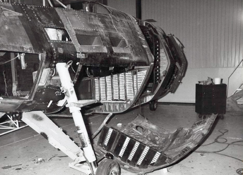
Composite structures offer inherent reliability and maintainability improvements because they eliminate corrosion, fastener related problems, and provide superior fatigue strength. However, susceptibility to impact damage, and repairability were concerns. To address impact damage, potential hazards were analyzed, and then impact tests were conducted to determine threshold material laminate configurations that would mitigate damage. Repair demonstrations were also performed to show how small damage could be repaired. This was generally done with wet lay-ups. However, for large scale damage situations from crashes or ballistic impact, a unique modular repair approach was developed. Since the fuselage was built up from large co-cured and bonded components, disassembly and replacement was considered too burdensome. The modular repair scheme divided the large components into smaller sections, defined with built-up composite repair strips. Thus, if large damage occurred within one of these zones, the damaged structure would be cut out along the repair strips, and a new module would be mechanically fastened to the built up repair strip using doubler straps. Essentially, cut along the dotted line. The following photograph shows how a large section of rear fuselage was cut out and then re-installed using this modular repair approach.
Modular repair demonstration
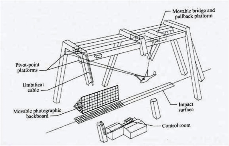
Crashworthiness
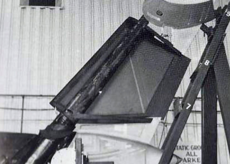
Full scale crash testing was conducted at the NASA Langley Impact Dynamics Research Facility (IDRF) in Hampton, Virginia. The IRDF is a 240-ft-high gantry structure that has been used for conducting full-scale crash tests of light aircraft and helicopters. To test its crashworthiness, the helicopter is suspended from the gantry, and when released is swung into the ground at a controlled speed and attitude.
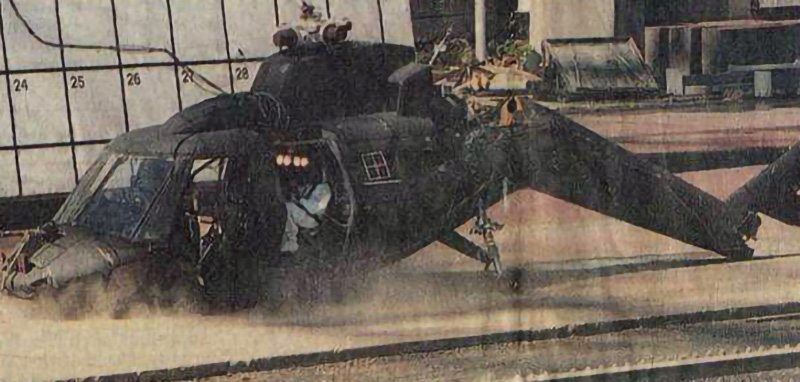
Two S-75 crash tests were conducted at this facility. The first test was conducted on the static test article, with a sink speed of 38 ft/sec, with 10 degrees of roll and pitch. The crash was deemed survivable, cabin volume was maintained, i.e. the roof did not cave in, and the anthropomorphic dummies in the cockpit and cabin did not sustain excessive deceleration forces. A subsequent crash test was conducted on the flight vehicle in 1999 to gather additional data and correlate crash analyses.
Diagram of the gantry structure at NASA’s Impact Dynamics Research Facility, showing how the helicopter is suspended for the test.
S-75 crash impact with the tailcone breaking off upon impact as intended.
Flight Test
A relatively short flight test program was conducted to demonstrate basic flying characteristics. This was a shakedown with a limited load survey, and vibration and handling qualities evaluations.
Flight Test over West Palm Beach, Florida
Achievements/Accomplishments
All of the ACAP technical requirements and objectives were met or exceeded. Table S75-2 summarizes these accomplishments.
Goal
Objective
Achieved
Weight Reduction
0.22
0.23
Cost Saving
0.17
0.2
Reliability Improvement
0.2
0.25
Ballistic Vulnerability
Minimize
Very Small
Payload
360 lbs.
708 lbs.
Maximum Speed (Vh)
140 kts.
141 kts.
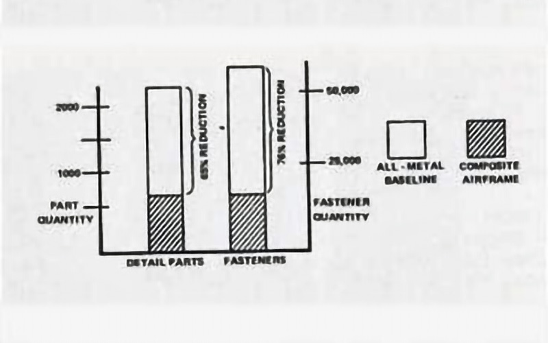
Affordability was a key objective, and reduced manufacturing costs were primarily achieved by reducing parts and fastener counts. The following diagram compares part and fastener counts for the composite airframe against its metal baseline.
Part and fastener count comparison
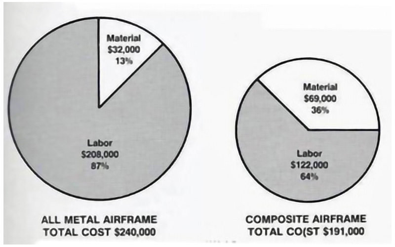
The resulting unit manufacturing costs for labor and material, expressed in 1990 dollars are shown in the following diagram. While material costs do increase, they were more than offset by reductions in labor.
Fuselage cost comparison
Epilogue
ACAP was a hugely successful program. It demonstrated that composites could be used in primary fuselage structures, could reduce weight, lower unit and life cycle costs, and satisfy all military requirements. A wide variety of design approaches, and manufacturing processes were developed that could be applied to future applications. Composite design processes, procedures and specifications were established. Equally important, was the creation of a skilled product development team.
In full recognition of the ability to produce composite structures that are cost competitive with conventional metal structures, a new business venture was created under the Sikorsky umbrella. The Sikorsky Composite Products unit was created to supply composite components to general aviation, and other aerospace manufacturers. This business subsequently evolved to become a Dow-UT subsidiary of United Technologies and Dow Corp, and then was subsequently sold to GKN Aerostructures, where it exists today.
The technology from ACAP also provided the confidence for the Boeing-Sikorsky LHX team to propose and then build a composite airframe for the RAH-66 helicopter.
References
USAAVRADCOM-TR-80-D-35A, “Airframe Preliminary Design for an Advanced Composite Airframe Program” March 1982, Bruce F. Kay and David Maass, Applied Technology Laboratory, U.S. Army Research and Technology Laboratories (AVRADCOM), Fort Eustis, Va., 23604
Technical paper “New Technology on ACAP” Danny Good and Bruce F. Kay, Presented at the AIAA/ASME/ASCE/AHS Structures, Structural Dynamics and Materials Conference, Lake Tahoe, Nevada, May 2-4, 1983
Brochure “The ACAP is Ready”, Published by the US Army Aviation Systems Command, Applied Technology Laboratory, July 1985
Static Test Techniques for Composite Structures Developed on the U.S. Army/Sikorsky ACAP, Hugh L. Kearney and Dan Good, Journal of the American Helicopter Society, Volume 30, July 1985
Technical paper “ Evolution of the ACAP Crash Energy Management System” Charles W. Clarke, Presented at the American Helicopter Society Forum 44, Washington, DC, May 1988