Background
The Rotor Systems Research Aircraft was a unique vehicle created to test advanced helicopter rotors in flight. The idea was to provide a capability to more fully explore the in-flight performance of new main rotor designs prior to committing them to a prototype or production helicopter program. Prior to the initiation of the RSRA program, new rotor configurations could only be tested in full scale on a stationary whirl stand or in a large scale wind tunnel. Because of these test envelopment limitations, there always was risk associated with new rotor configuration when they were first flow on the helicopters for which they were designed. To reduce this risk, NASA and the Army concluded that a test aircraft dedicated to safely explore the performance, stability boundaries and loads generated by a new rotor throughout its flight envelope would be worth developing. Having such an aircraft would also encourage the design and flight test of unique rotor configurations that would extend rotary wing technologies. These considerations are what launched the RSRA in the early 1970s.
In the summer of 1971, NASA and the Army put out an RFP for a “Rotor Test Vehicle Predesign Study”. Sikorsky and Bell responded to this RFP and were awarded nine-month study contracts. A primary requirement was to determine what was practical for such a vehicle and how to minimize development cost and risk.
In July 1972 Sikorsky reported to NASA and the Army on the results of the Predesign study. By now the aircraft were known as “Rotor Systems Research Aircraft”, or RSRA. To keep program costs down as much as possible, the use of existing aircraft or components was encouraged. The size of the test aircraft was defined by a requirement that all rotors to be tested had to be small enough to fit in the NASA Ames 40 x 80 wind tunnel. The aircraft itself had to be mountable in the 40 x 80 tunnel.
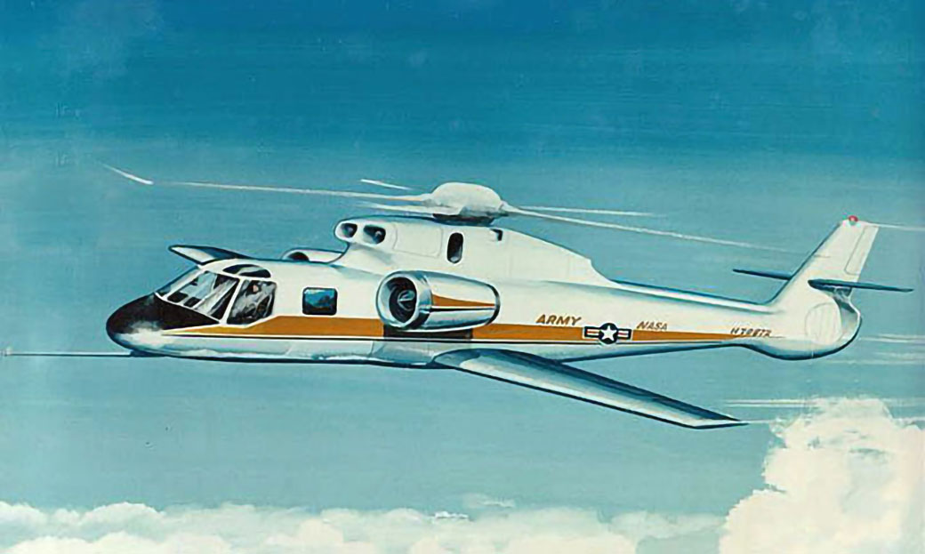
Sikorsky’s design included a new fuselage with the dynamic system from a 3700 horsepower “roller” gearbox then under development at Sikorsky under an Army contract. It used General Electric TF-34 turbofan engines for auxiliary propulsion. It had two interchangeable wings, one with a 348 sq. ft. area and a 45.7 ft. span for the 100 to 200 knot speed range, and one with a 184 sq. ft. area and a 33.3 ft. span for speeds up to 300 knots. It included a variable wing incidence; main rotor, tail rotor, wing and auxiliary engine force and moment balance systems; a rotor vibration isolation feature, and a fly-by-wire control system from the pilot’s station. In order to further reduce risk when testing advanced rotors never before flown, a crew escape system, similar to those on fixed-wing aircraft, was included. The desired variable main rotor shaft tilt system was deemed too complex for the value gained, and was eliminated. The aircraft used a fan-in-fin anti-torque system with a series of louvers to cover it up in high speed.
As a result of the Predesign Studies and other analysis done by the parties, NASA and the Army released an RFP for the RSRA program in 1973. On May 15, 1973 Sikorsky submitted its proposal. Although quite similar to the Predesign study aircraft, some practical changes had been made. It had been desired to use the TF-34 engine installation from the Fairchild-Republic A-10, with its side-mounted General Electric turbofan engines. This did not work out contractually, so the top-mounted TF-34 installation from the Lockheed S-3A was substituted, requiring a rather awkward curved mounting structure to be included on the aircraft. The 3700 horsepower roller main gearbox development program had not proceeded as planned, and a production SH-3 2500 horsepower main gearbox was proposed. The Predesign study fan-in-fin anti-torque system, which had been under a then-terminated separate development program, was no longer practical within program costs, and a conventional tail rotor was used. The remainder of the design was virtually the same as shown in the Predesign study.
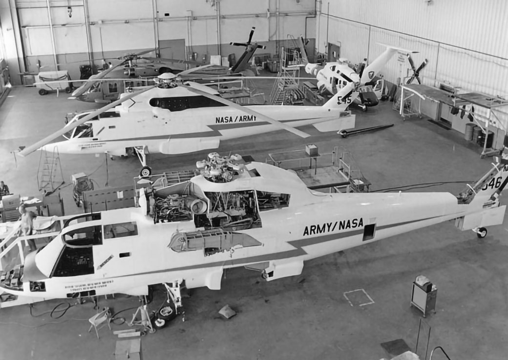
Sikorsky won the RSRA contract and initiated the design and fabrication of two aircraft.
Initial flight tests were conducted at the Sikorsky factory in Stratford Connecticut. In July 1977, the first aircraft was flown to NASA’s Wallops Island Flight Test Facility on Virginia’s eastern shore. The flight testing was done there since it was a large NASA-controlled facility with fixed-wing runways which would be needed for some compound mode flight testing. It was also convenient to the NASA Langley facility, which had the NASA lead on the project, and to the Army’s Ft. Eustis, the Army’s lead facility on the program. Sikorsky had a team of approximately twenty engineers, technicians, and pilots stationed at Wallops. NASA and the Army also had a staff on sight for the test program.
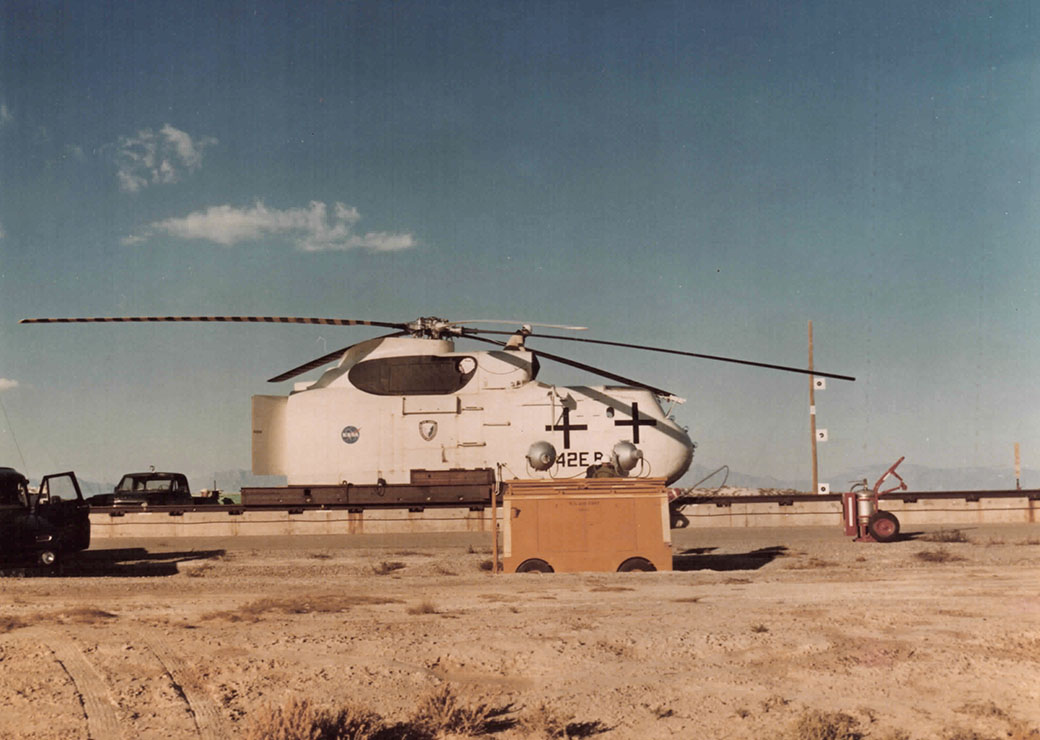
One of the most interesting facets of the RSRA was the crew escape system. Although it couldn’t be tested in flight, the full system was tested at the Air Force test facility at Holloman Air Force base in New Mexico. In November, 1977 the first flight with the fully qualified escape system took place.
The first flight in the full compound configuration took place on April 10, 1978. After Sikorsky completed the contractor development tests on it, aircraft #2 was delivered to NASA Ames in the fall of 1978. Aircraft #1 continued its test program at Wallops Island, with the rotor vibration isolation system installed.
The Sikorsky flight test phase was concluded on August 17, 1979. The aircraft had flown a total of 60.1 flight hours performing necessary development tests and opening up the envelope to that required by the Government for initial NASA/Army tests. In September RSRA #1 was delivered to NASA Ames to join aircraft #2. At that time, Sikorsky’s contracted RSRA program was concluded, with the exception of final reports and other close-out tasks. NASA did contract with Sikorsky for two years of flight test support at Ames.
By the early 1980s both NASA and the Army were directing the majority of their rotary wing research funding to the tilt rotor concept. With the exception of a few minor tests this brought the RSRA program to a halt before it was able to perform its intended tasks.
RSRA was soon reincarnated as the test vehicle for the X-Wing concept. X-Wing used a rigid four bladed rotor which was stopped in flight to become an “X” wing. The critical technology was the rotor starting and stopping sequence. With the RSRA’s fixed wing, which allowed initial start/stop conversions without requiring the rotor/wing to maintain lift, the RSRA was the ideal test vehicle for X-Wing. The X-wing program is described separately in this Sikorsky product history.
Configuration Features
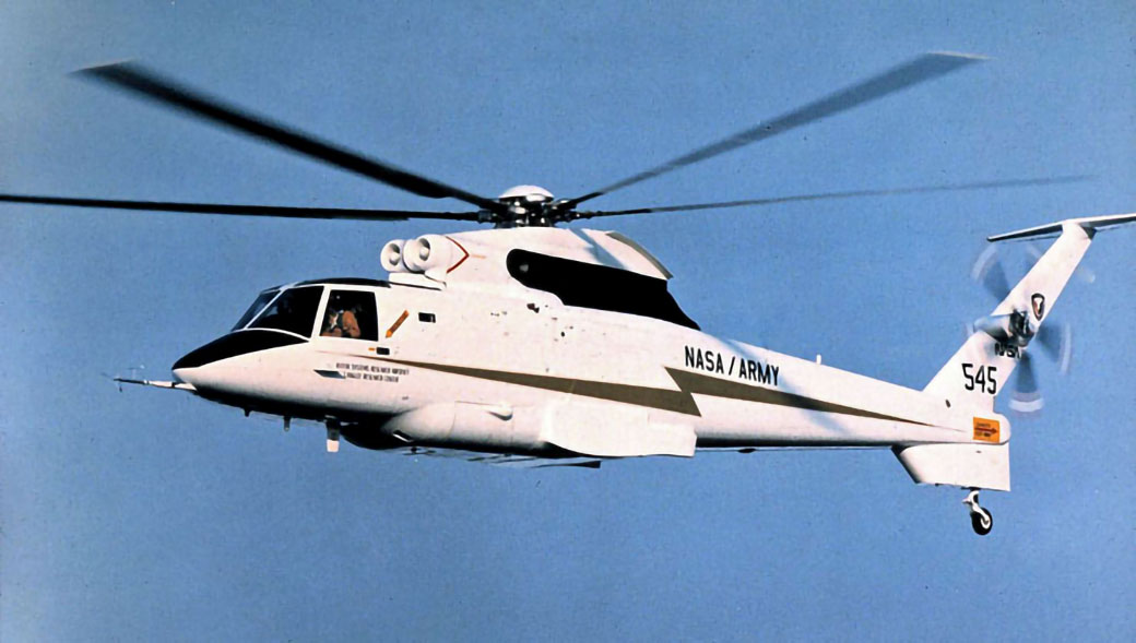
The RSRA fuselage was all new, designed for low drag and for the high dynamic pressures required to fly up to the 340 knot maximum structural design speed. It had a two man side-by-side cockpit and a flight test engineer’s station in the cabin. The cabin was approximately six feet long and also accommodated test equipment on racks along the aft bulkhead. Large drag brakes were included on the lower empennage.
The drive system was taken directly from Sikorsky’s SH-3/S-61 series of aircraft. The delivered rotor was also taken from the SH-3/S-61. This rotor was, of course, to be used only for the initial shake-down flight testing. Once the aircraft was delivered and checked out by NASA/Army, new rotors were to be installed
The flight controls were fly-by-wire from the evaluation pilot’s station (left side of the cockpit). Although the sticks and pedals looked conventional, they were not connected mechanically to the aircraft control system. An electronic connection was made to the safety pilot’s controls on the right crew station. Thus the second pilot became the back-up or safety pilot if the electronic controls were not functioning as designed. Digital computers were used to modify and augment the inputs from the evaluation pilot’s controls as desired by the testing being done, before they were inputted into the safety pilot’s mechanical controls. The flight control computers also controlled, with limited authority, numerous other actuators in the mechanical control system.
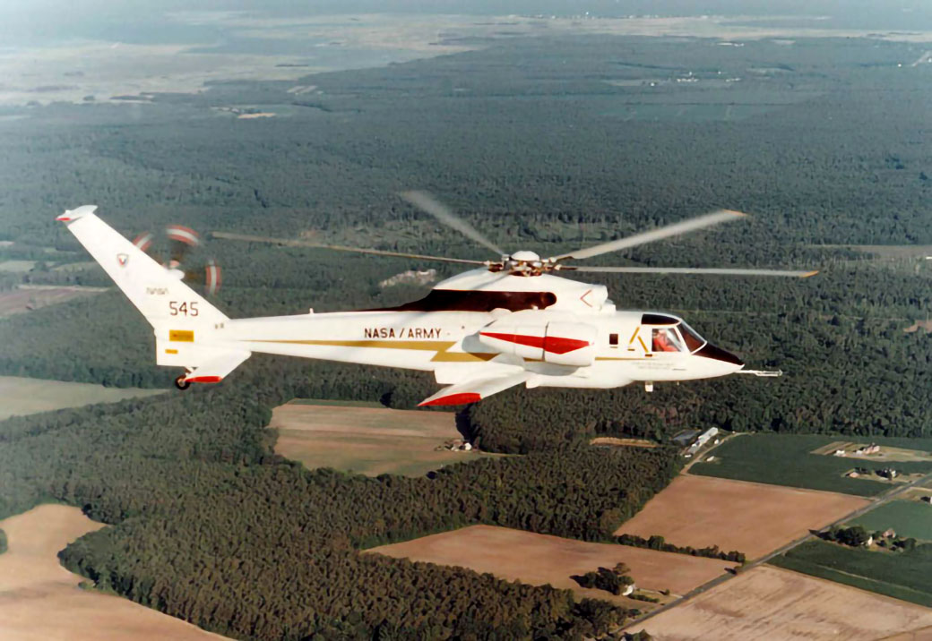
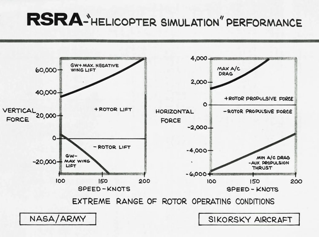
The concept of two wings, one for medium speed and one for high speed, from the Predesign study was found not to be required. A single large variable incidence wing with high-lift devices was provided to offload the rotor in forward flight or, with negative incidence, to overload the rotor in level flight. The wing was easily removable for testing as a basic helicopter. The TF-34 auxiliary engines provided horizontal propulsion to test rotors when they were not producing the horizontal thrust necessary for level flight. These also had to be easily removed. A variable high-drag device was included in the tail to overload the rotor’s forward thrust requirements
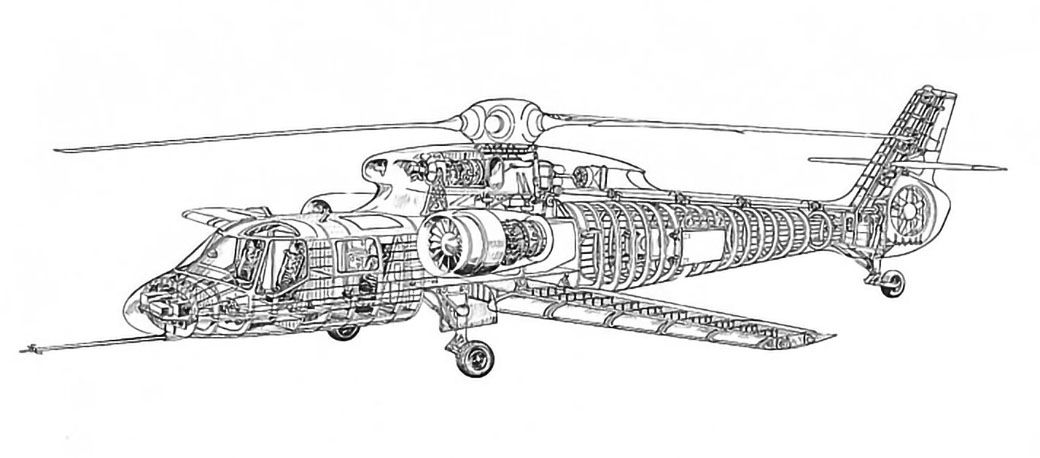
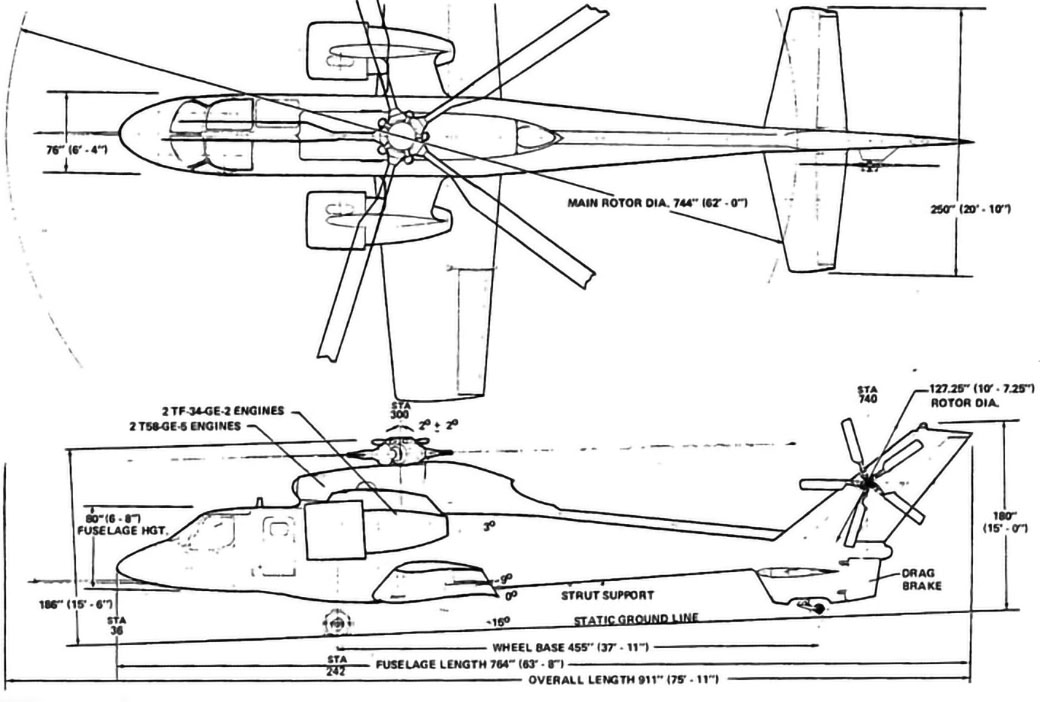
General Arrangement Drawing
Mission Systems
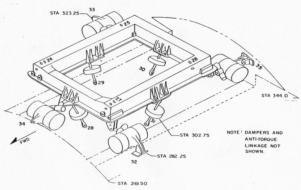
The main transmission was mounted on a force/moment measuring system to give accurate data for the rotors being tested. Seven load cells were mounted in orthogonal directions to provide data in aircraft coordinates. Necessary redundancy was included in the attachment of the transmission mounting frame to the fuselage
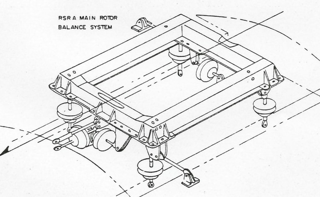
An alternate transmission mounting system added vibration isolators between the mounting frame and the fuselage. This was a “focused pylon” system with ground adjustable cant angles and variable spring rates for tuning and attenuation, with control of the resulting static displacements being provided by servo controlled hydraulic centering. Four inplane soft isolators and four nominally vertical load cells were used. An alternate design for other types of rotors used seven soft isolators.
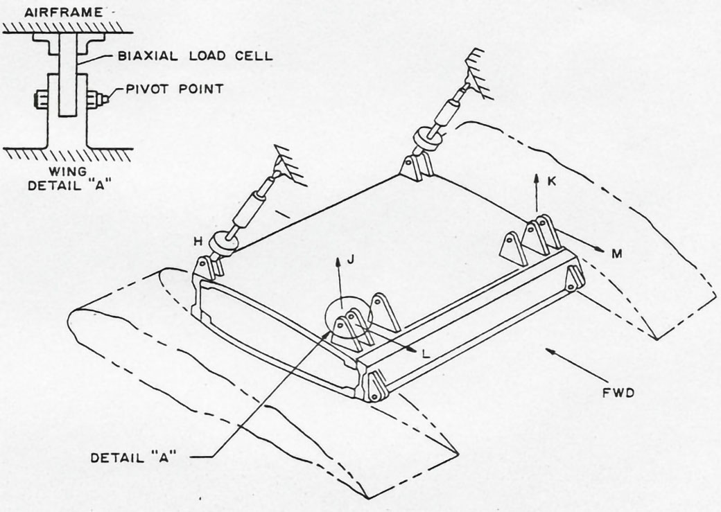
The wing was mounted low and included the variable incidence feature, with in-flight variation from 15 degrees nose up to 9 degrees nose down. This mounting system also included accurate load cells to measure wing forces and moments
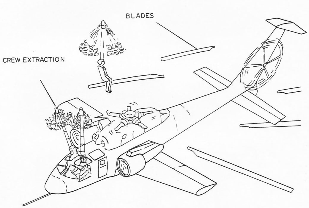
One of the truly unique features of the RSRA was the inclusion of a crew escape system. This was designed to be similar to those used on fixed wing aircraft, but had to deal with the rotating rotor overhead blocking safe extraction of the flight crew. It had been determined that trying to eject the crew downward would not be acceptable due to human factors issues plus the need for RSRA to operate on many flights close to the ground.
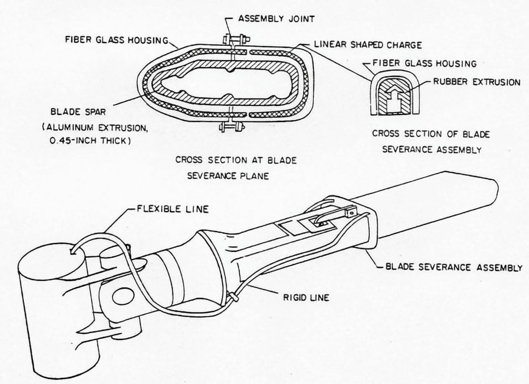
Thus, a blade severance system was developed. This used shaped explosive charges around the blade roots to sever the blade spars and blow the blade away from the aircraft. To assure that no blade was thrown forward where the extracting pilots might hit it, or aft where it might strike the empennage, a two stage blade severance was used. On the five bladed baseline rotor, first three blades were severed, being flung to the sides of the aircraft. After another 72 degrees of rotation the last two blades were also thrown to the sides. The crew extraction system itself was developed by Stanley Aviation, Inc. using small rockets which pulled the crewman up out of the aircraft, rather than the more conventional rocket mounted on the seat itself, as is used in most fixed wing applications
Although this system could not be practically tested in flight, it did undergo numerous ground tests which culminated in a full system test at speed being conducted on the Holloman Air Force Base “Long Track” in New Mexico. The RSRA system became the first and only crew escape system qualified for use on a flight rotary wing vehicle.
General Characteristics and Performance
| S-72 RSRA Characteristics and Performance | |
|---|---|
| Maximum Test Speed | 300 knots |
| Design Dive Speed | 340 knots |
| Endurance @ 300 kts | 30 mins |
| Design GW, Compound | 26,392 lbs |
| Empty Weight, Compound | 20,812 lbs |
| Design GW, Helicopter | 20,276 lbs |
| Empty Weight, Helicopter | 14,490 lbs |
| Fuselage Length | 63 ft 8 ins |
| Maximum Height | 15 ft 0 ins |
The mission of the RSRA was to test advanced rotors through the full range of their lift and horizontal thrust envelope.
Related Models
After delivery to NASA/Army the aircraft were used for some minor rotor tests. The major test program involved the development of the X-wing. This involved a four bladed rotor which was stopped in flight to become a fixed “X” wing. The X wing is the subject of a separate section of this Sikorsky Product History. An interesting part of the X-wing program was flying the RSRA without a rotor. This was to prove that the RSRA could be used for X-wing starting and stopping tests, where rotor lift would be zero. It also demonstrated the first Sikorsky designed fixed wing aircraft since the days of the flying boats.
Additional Information Sources
American Helicopter Society paper Fifty Years of Sikorsky High Speed Concepts, Arthur W. Linden. Presented at the 64th AHS Annual Forum, Montreal, Canada, April 29 – May 1, 2008.